Method of increasing friction material utilization for carbon brakes

a technology of carbon disc brakes and friction material, which is applied in the direction of axially engaging brakes, brake types, actuators, etc., can solve the problems of significant amount of material ground, worn one-piece discs, and inability to make good economic sense of disc storage for aircraft owners, so as to increase the utilization of carbon discs in aircraft brakes

Inactive Publication Date: 2006-09-12
HONEYWELL INT INC
View PDF19 Cites 13 Cited by
  • Summary
  • Abstract
  • Description
  • Claims
  • Application Information

AI Technical Summary

Problems solved by technology

Discarding still usable discs does not make good economic sense for aircraft owners.
However, upon completion of the tours, such “Balanced” design ended up producing many worn one-piece discs, which had to have a significant amount of material ground off if they were to be 2-for-1 refurbished with other one-piece discs.
Grinding off usable carbon also does not make good economic sense for aircraft owners.

Method used


Image

  • Method of increasing friction material utilization for carbon brakes
  • Method of increasing friction material utilization for carbon brakes
  • Method of increasing friction material utilization for carbon brakes

Examples


Embodiment Construction

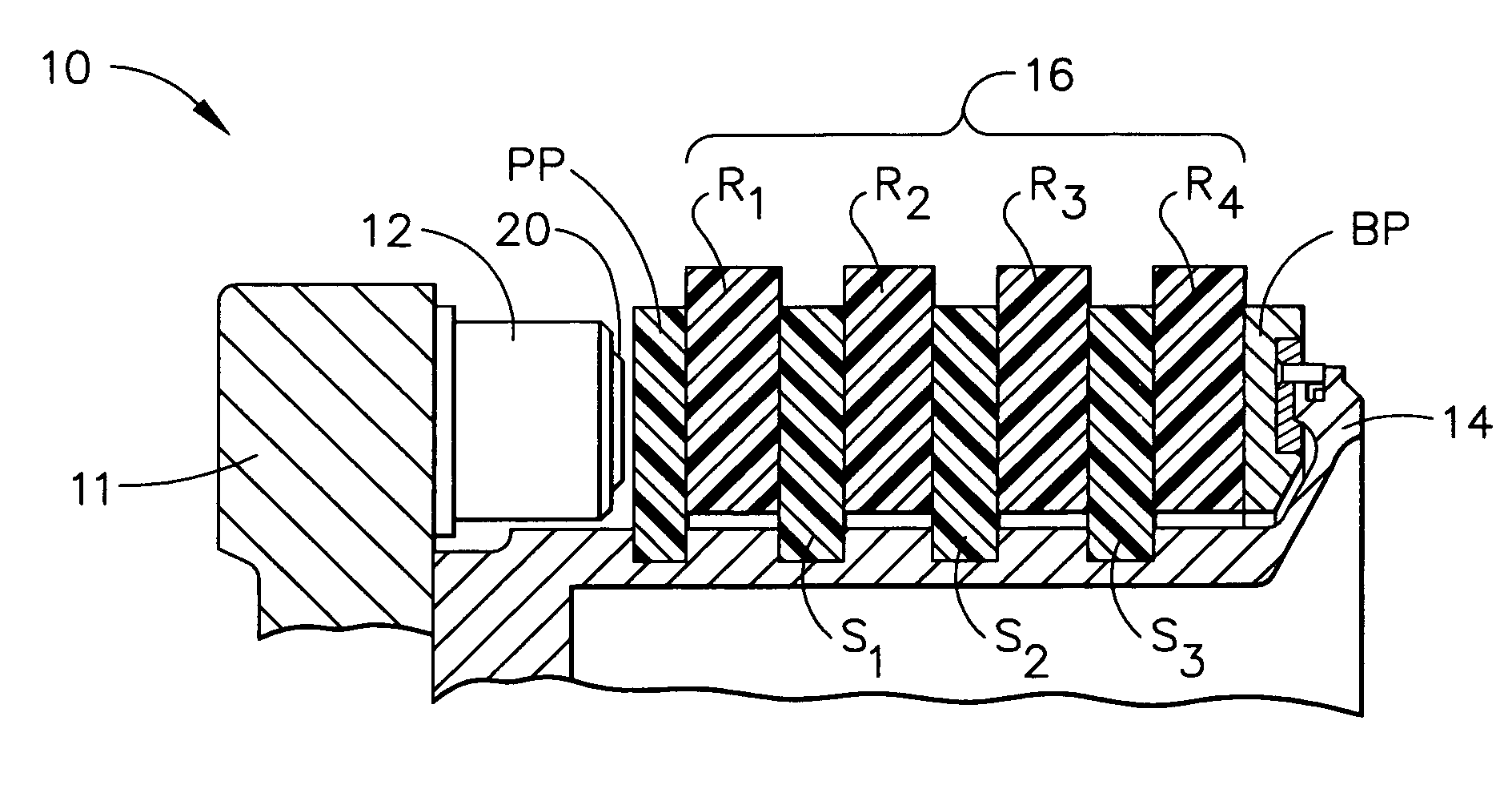
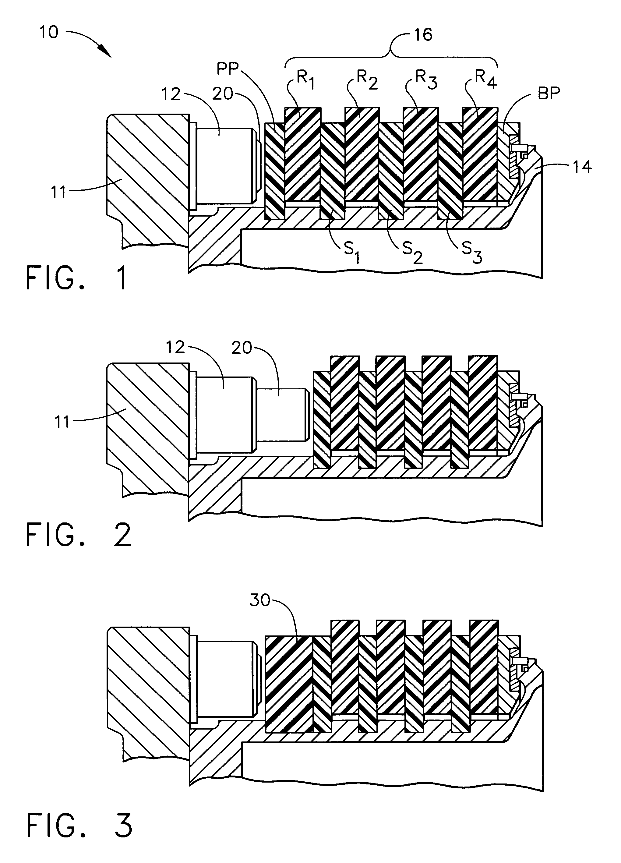
[0021]Reference is first to FIG. 1, where a first configuration of a rotor / stator assembly of an aircraft carbon brake unit 10 is illustrated. The brake unit 10 includes a torque tube 14 attached to a piston housing 11 by a plurality of bolts (not shown). The piston housing 11 includes a piston bushing assembly 12 with a piston 20. The heat stack designated generally by reference numeral 16 includes carbon rotor discs, R1–R4, that engages, via spline and slot arrangements, the surrounding wheel (not shown), as is well known in the art, and alternating carbon stator discs, S1–S3, engaging the torque tube 14 via the well known spline and slot arrangements. At one end of the heat stack 16 is a pressure plate, PP, between the piston 20 and the rotor R1. At the other end of the heat stack 16 is a back plate, BP, which engages the torque tube 14 via a steal structure, as is also well known in the art of carbon disc brakes. The actual number of stages or disc pairs will vary from brake to ...


PUM


Abstract

A method of increasing carbon disc utilization in aircraft carbon brakes. A brake (10) is initially assembled with a heat stack (16) of alternating thick rotors (R1–R4) and thin stators (S1–S3). When the piston (20) is fully extended, it is retracted and a spacer (30) is inserted between the piston (20) and the original heat stack (16). The brake (10) is then subjected to a another half tour. After this half tour, the brake (10) is overhauled, and the now-thin discs (S1–S3, PP and BP) are replaced with thick discs to form another heat stack (50). For the next half tour, no spacer is used between the piston (20) and the heat stack (50). At the end of this half tour and the piston (20) is fully extended, a spacer (70) is inserted between the piston (20) and the heat stack (50). The heat stack (50) remains unchanged. For the next half tour, it is accomplished with the spacer (70). When this half tour is completed, the worn out rotors are replaced with new thick rotors and the process can be repeated.

Description

TECHNICAL FIELD AND INDUSTRIAL APPLICABILITY OF THE INVENTION[0001]The present invention generally relates to carbon disc brakes, and more particularly to multi-disc carbon brake systems used in aircraft's landing systems.BACKGROUND OF THE INVENTION[0002]Aircraft brakes typically include a plurality of stator discs and rotor discs which are compressed together during the braking operation of an aircraft. The stator discs and rotor discs are normally arranged in alternating fashion in order to form a brake disc stack.[0003]The stationary, stator discs of the disc stack are arranged in a non-rotating position surrounding an aircraft brake structure or shaft. The rotating, rotor discs are secured to a periphery of the aircraft wheel or shaft and are normally free to rotate with the aircraft wheel when the brake is not in use.[0004]A brake housing may include a plurality of pressure piston actuators that are arranged to provide the compressive, braking force that forces the stator discs...

Claims


Application Information

Patent Timeline
Patent Type & Authority Patents(United States)
IPC IPC(8): F16D55/36F16D55/00
CPCF16D55/36F16D2200/0052F16D2055/0095
Inventor MCAFEE, DAVID D.FRYSKA, SLAWOMIR T.
Owner HONEYWELL INT INC
Why Eureka
Try Eureka