Air assist fuel injector guide assembly

a fuel injector and guide assembly technology, applied in the direction of fuel injectors, liquid fuel feeders, machines/engines, etc., can solve the problems of difficulty in manufacturing hollow poppets of such conventional failure or improper operation of air assist fuel injectors,

Inactive Publication Date: 2006-09-12
SYNERJECT
View PDF38 Cites 21 Cited by
  • Summary
  • Abstract
  • Description
  • Claims
  • Application Information

AI Technical Summary

Problems solved by technology

Unfortunately, the finish dimensions of these bearing surfaces are typically set during complex and time consuming grinding operations.
If these finish dimensions are not precise, the air assist fuel injector may fail or function improperly because of improper alignment of the poppet.
Additionally, the hollow poppets of such conventional air assist fuel injectors are also difficult to manufacture.

Method used


Image

  • Air assist fuel injector guide assembly
  • Air assist fuel injector guide assembly
  • Air assist fuel injector guide assembly

Examples


Embodiment Construction

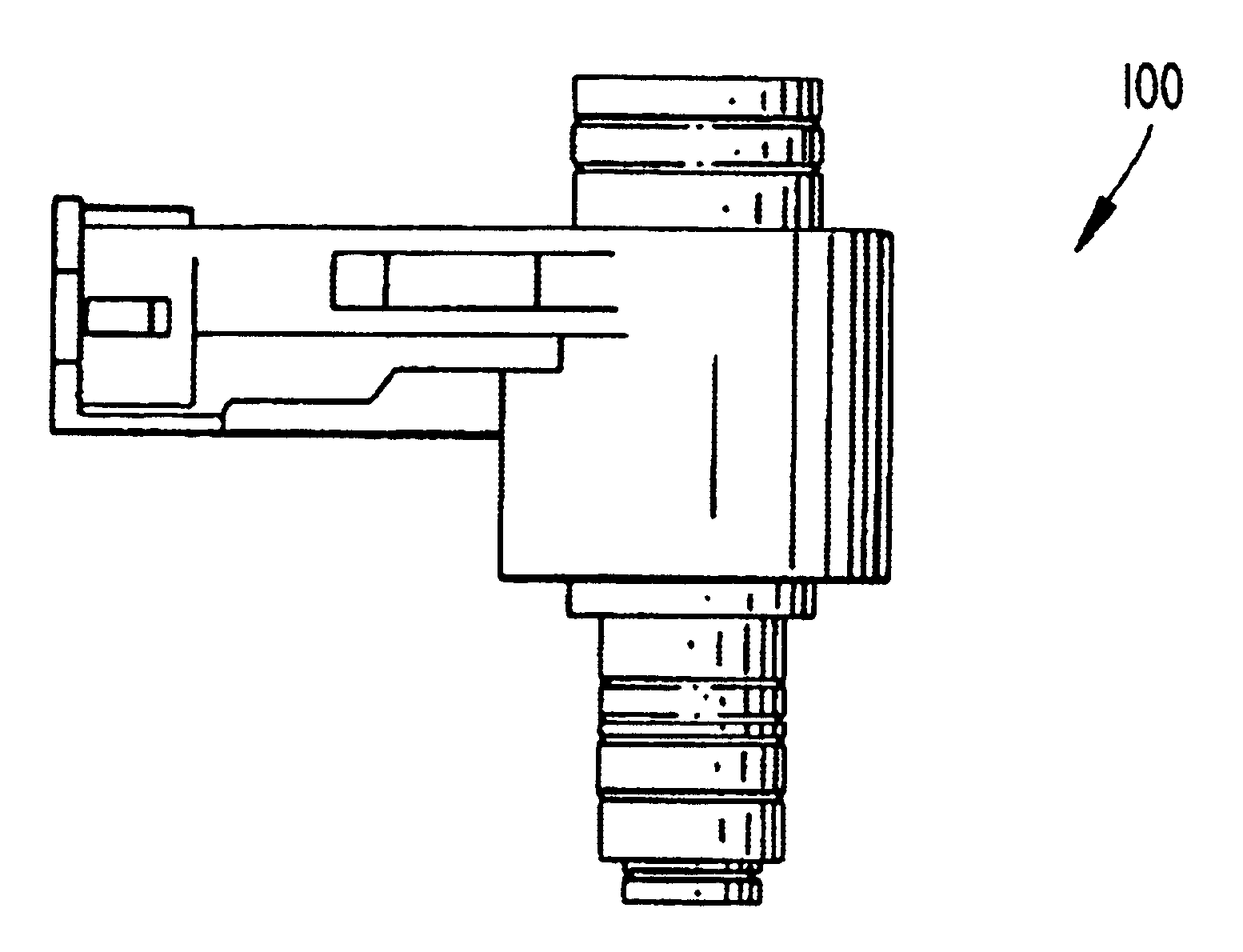
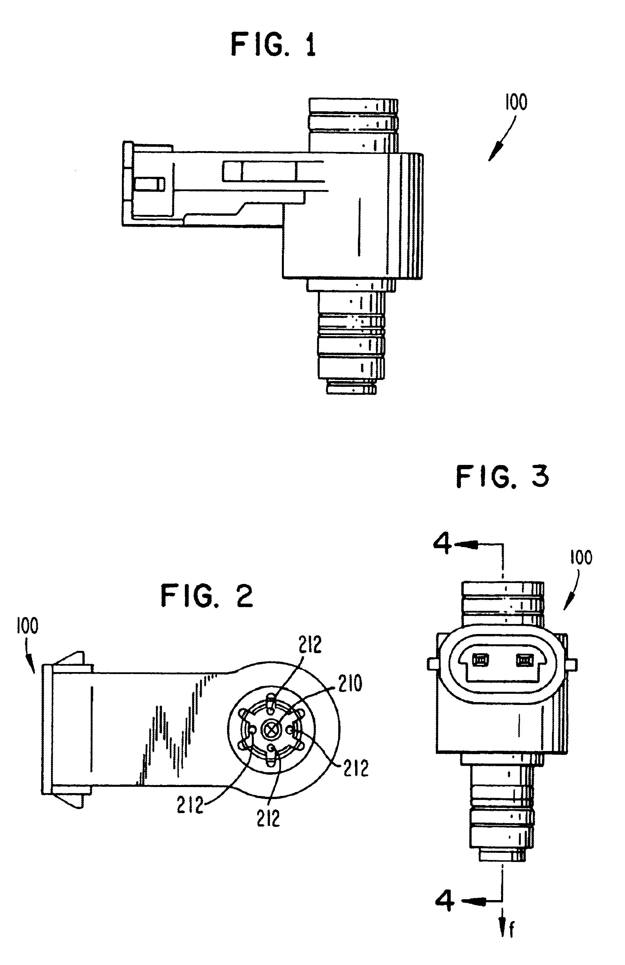
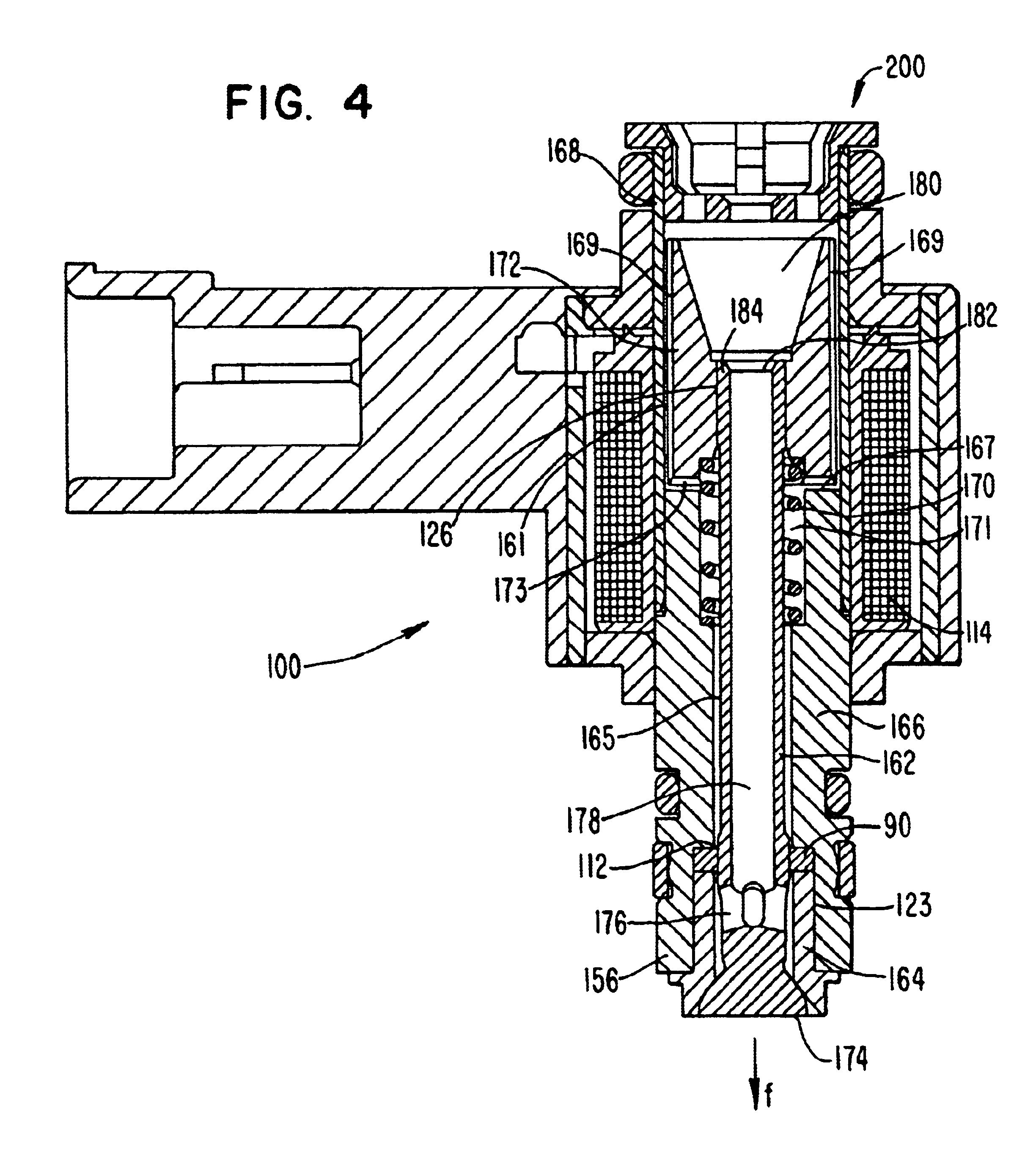
[0058]FIGS. 1-7 illustrate one embodiment of an air assist fuel injector 100 having an insert 90 for guiding movement of a poppet 162 in accordance with the present invention. The air assist fuel injector 100 is configured for use with a two-stroke internal combustion engine. However, alternative embodiments of the air assist fuel injector 100 are configured for operation with other engines. For example, the air assist fuel injector 100 may be configured for operation with a four stroke internal combustion engine. The air assist fuel injector 100 is configured to utilize pressurized gas to atomize low pressure liquid fuel, which together travel through the air assist fuel injector 100 along a direction of flow f as indicated in FIGS. 3 and 4. As illustrated in FIG. 5, the air assist fuel injector 100 includes two primary assemblies: an actuator assembly 110 and a valve assembly 160.

[0059]The actuator assembly 110 includes a solenoid coil 114 of conductive wire wrapped around a tubul...


PUM


Abstract

Air assist fuel injectors having one or more inserts that guide movement of a poppet, and an air assist fuel injector having a solid poppet.

Description

BACKGROUND OF THE INVENTION[0001]1. Field of the Invention[0002]The present invention relates to air assist fuel injectors, and, more particularly, to inserts that guide movement of the poppets of such air assist fuel injectors and to air assist fuel injectors having solid poppets.[0003]2. Description of the Related Art[0004]Conventional fuel injectors are configured to deliver a quantity of fuel to a combustion cylinder of an engine. To increase combustion efficiency and decrease pollutants, it is desirable to atomize the delivered fuel. Generally speaking, atomization of fuel can be achieved by supplying high pressure fuel to conventional fuel injectors, or atomizing low pressure fuel with pressurized gas, i.e., “air assist fuel injection.”[0005]Conventional air assist fuel injectors are typically mounted to a rail, which houses a conventional fuel injector and also defines a mount for the air assist fuel injector. The conventional fuel injector and the rail are configured such th...

Claims


Application Information

Patent Timeline
Patent Type & Authority Patents(United States)
IPC IPC(8): B05B1/30F02M51/02F02M51/06F02M61/04F02M61/08F02M67/12F02M69/08
CPCF02M51/0682F02M61/042F02M69/08F02M67/12F02M61/08
Inventor KILGORE, DAVIDROGERS, WILLIAM JUNEDILLON, SCOTT P.MASCHKE, GARY LEEKIMMEL, JAMES ALLEN
Owner SYNERJECT
Why Eureka
Try Eureka