Stabilizer and air leaf suspension using the same

a technology of stabilizer and air suspension, which is applied in the direction of twisting springs, mechanical equipment, transportation and packaging, etc., can solve the problems of conventionally unattainable, extreme swift effectiveness of stabilizer, etc., and achieve the effect of improving driving stability at cornering, reducing the effect of slipping and rolling of the chassis

Inactive Publication Date: 2006-09-12
NHK SPRING CO LTD
View PDF14 Cites 7 Cited by
  • Summary
  • Abstract
  • Description
  • Claims
  • Application Information

AI Technical Summary

Benefits of technology

[0020]As a result, obtained is conventionally unattainable, extreme swift effectiveness of the stabilizer. Rolling of the chassis is efficiently suppressed by applying anti-rolling force on the chassis before occurrence of great rolling of the chassis. Thus, according to the invention, driving stability at cornering is substantially improved in comparison with conventional stabilizers where greater anti-rolling force acts on the chassis after occurrence of great rolling of the chassis.
[0021]Since the stabilizer links are arranged upwardly convergently according to the invention, center lines of the stabilizer links are crossed at a higher position which becomes a rolling center of the chassis so that shortened is distance between the center of rolling and the center of gravity of the vehicle. Such shortened distance also has an effect of suppressing the occurrence of rolling moment.
[0022]In the stabilizer according to the invention, the stabilizer bar may be made of a U-shaped pipe with opposite reduced-diameter ends over which lower ends of the stabilizer links may be fitted via rubber bushes and secured thereto by snap rings for prevention of slip-off, which enables the stabilizer bar as the main component to be provided by a hollow pipe. As a result, the stabilizer can be substantially reduced in weight and produced with less cost since the constituent parts are inexpensive and fewer in number.
[0024]With such air leaf suspension thus constructed, the stabilizer used has swift effectiveness unobtainable in the prior art and can attain both the riding comportability of the vehicle due to lowered spring constant and excellent anti-rolling performance, so that an air leaf suspension can be obtained which is light in weight, less expensive and has improved riding comportability.

Problems solved by technology

As a result, obtained is conventionally unattainable, extreme swift effectiveness of the stabilizer.

Method used


Image

  • Stabilizer and air leaf suspension using the same
  • Stabilizer and air leaf suspension using the same
  • Stabilizer and air leaf suspension using the same

Examples


Embodiment Construction

[0031]FIGS. 3 to 7 show an embodiment of the invention in which parts similar to those in FIGS. 1 and 2 are represented by the same reference numerals.

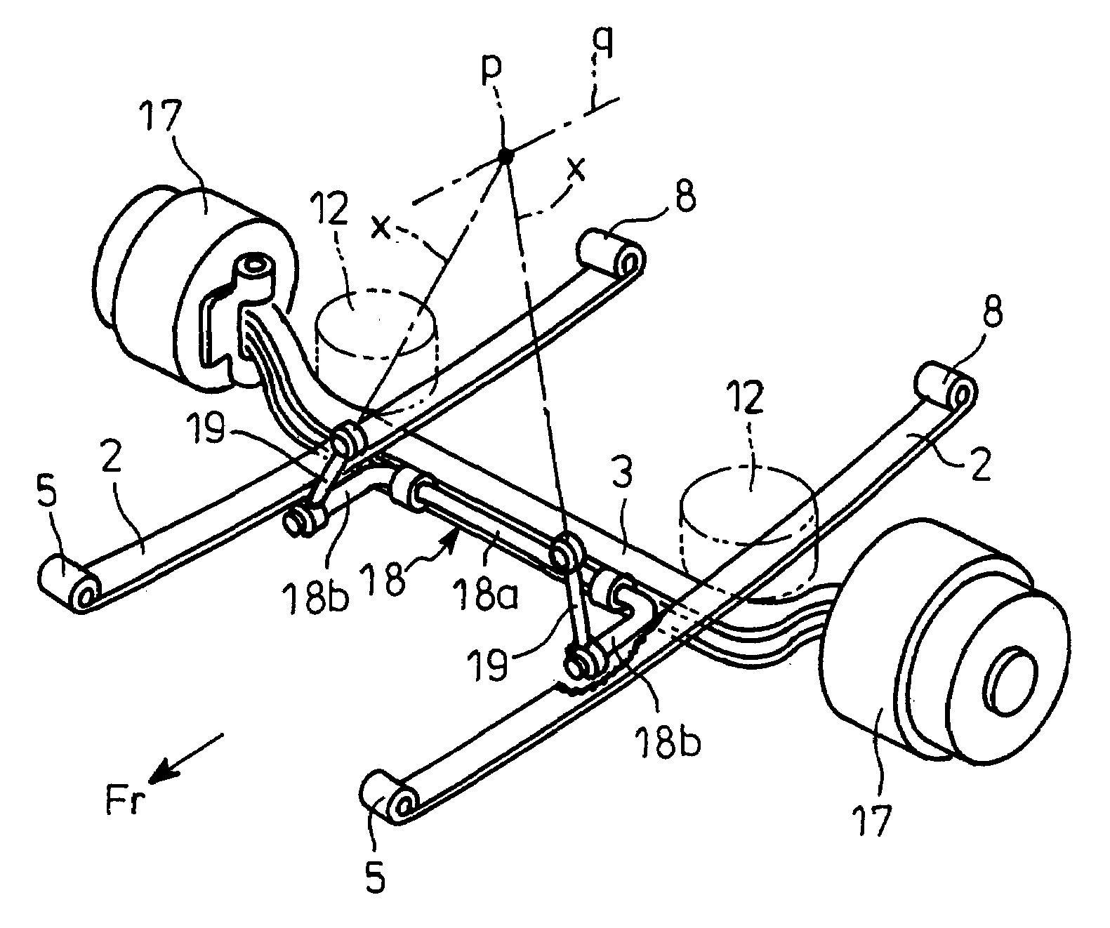
[0032]As best shown in FIG. 3, the embodiment applied is an air leaf suspension with leaf and air springs in combination substantially similar to that shown in FIG. 2. More specifically, the stabilizer of FIG. 2 is substituted by a stabilizer detailed hereinafter.

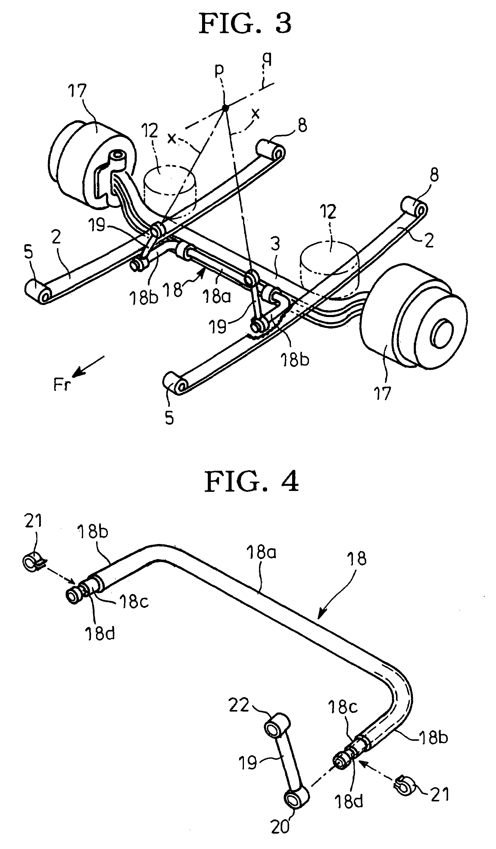
[0033]A portion 18a of an stabilizer bar 18 which is U-shaped when seeing from above extends along and is rotatably fitted to an axle 3. Forwardly protruded longitudinal ends 18b of the stabilizer bars 18 are connected to the respective side rails 1 thereabove (see FIG. 5) via a pair of upwardly convergent stabilizer links 19.

[0034]Extension center lines x of the stabilizer links 19 are crossed together at a laterally intermediate higher position p through which an axis q of rolling passes longitudinally of the vehicle.

[0035]As shown in FIG. 4, the stabilizer bar 18 is made o...


PUM


Abstract

Disclosed are a stabilizer with conventionally unattainable, extreme swift effectiveness and an air leaf suspension using the stabilizer. The stabilizer has a stabilizer bar 18 which is U-shaped when seeing from above and which has a portion 18a laterally extending along and rotatably connected to an axle 3, and a pair of upwardly convergent stabilizer links 19 which connect opposite longitudinally extending ends of the stabilizer bar to a chassis frame side above them.

Description

CROSS-REFRENCE TO RELATED APPLICATION[0001]This application is related to and claims priority, under 35 U.S.C. § 119, from Japanese Patent Application No. 2002-263998, filed in the Japanese Patent Office on Sep. 10, 2002, the entire contents of which is hereby incorporated by reference herein.BACKGROUND OF THE INVENTION[0002]1. Field of the Invention[0003]The present invention relates to a stabilizer and a leaf suspension using the same.[0004]2. Discussion of Background[0005]There are various suspensions for hanging axles from chassis frames. Among them, a leaf suspension with layered leaf springs has been widely used for vehicles such as trucks since it is of simple structure, less expensive, superior in strength and highly durable.[0006]FIG. 1 shows an example of such leaf suspension in which reference numerals 1 denote a pair of opposite, side rails which extend longitudinally of a vehicle and form parts of a chassis frame; 2, two-layered leaf springs extending along the side rai...

Claims


Application Information

Patent Timeline
Patent Type & Authority Patents(United States)
IPC IPC(8): B60G21/055B60G9/02B60G11/04B60G11/44B60G11/46
CPCB60G9/025B60G11/44B60G11/465B60G21/0551B60G11/04B60G2300/45B60G2200/30B60G2200/31B60G2200/346B60G2202/112B60G2202/135B60G2202/152B60G2204/1224B60G2204/422B60G2204/4402B60G2204/45B60G2206/427B60G2300/026
Inventor MOMIYAMA, FUJIO
Owner NHK SPRING CO LTD
Why Eureka
Try Eureka