Zoom lens
a zoom lens and zoom technology, applied in the field of zoom lenses, can solve the problems of difficult to achieve a zoom ratio greater than 2, increase the structure complexity of the lens barrel, and greatly change the overall length of the optical system, and achieve excellent optical performance, high zoom ratio, and correction of chromatic aberration
- Summary
- Abstract
- Description
- Claims
- Application Information
AI Technical Summary
Benefits of technology
Problems solved by technology
Method used
Image

Examples
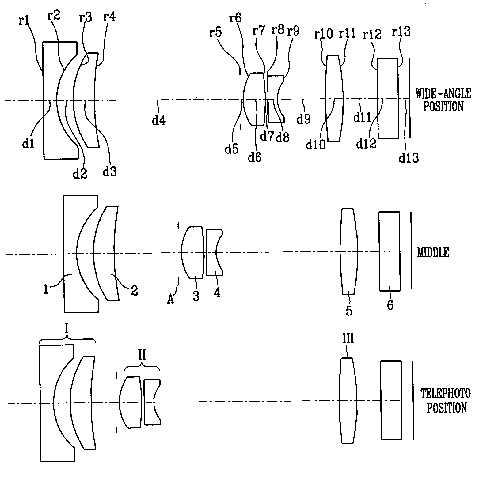
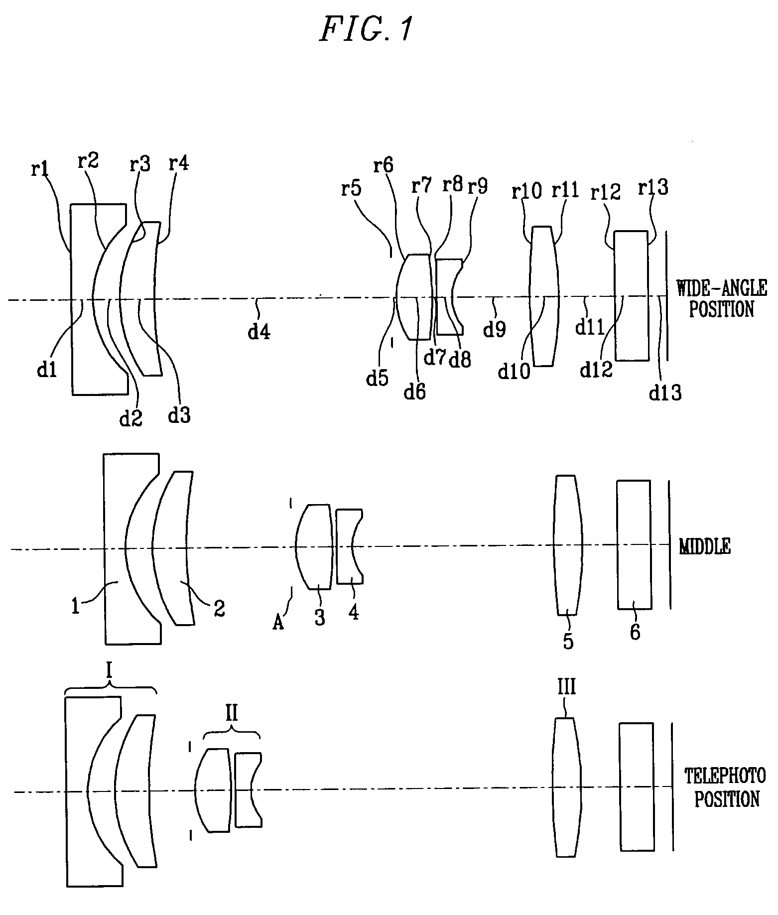
first embodiment
[0074]Various values associated with the component lenses of the zoom lens according to the present invention are listed in Table 1.
[0075]
TABLE 1FaceThickness,RefractiveVarianceNumberRadius of Curvature (r)Distance (d)Index (nd)(v)*1184.865001.3200001.806140.74*25.385001.590000 38.830001.8600001.846723.78 425.84700D1 5∞0.220000*64.326002.0900001.693553.20*7−16.927000.220000 816.431000.9400001.821124.06*93.77900D21051.571001.5900001.772549.6211−19.12800D312∞2.0000001.516864.2013∞1.00011
[0076]The symbol “*” indicates an aspheric surface. Aspheric surface coefficients can be expressed by the following equation:
[0077]x=c2y21+1-(K+1)c2y2+Ay4+By6+Cy8+Dy10[Equation1]
where x is the distance along the optical axis from the vertex of the lens; y is the distance in the direction vertical to the optical axis; c is the inverse (1 / R) of the radius of curvature on the vertex of the lens; K is the conical constant; and A, B, C, and D are aspheric surface coefficients.
[0078]The aspheric surface...
second embodiment
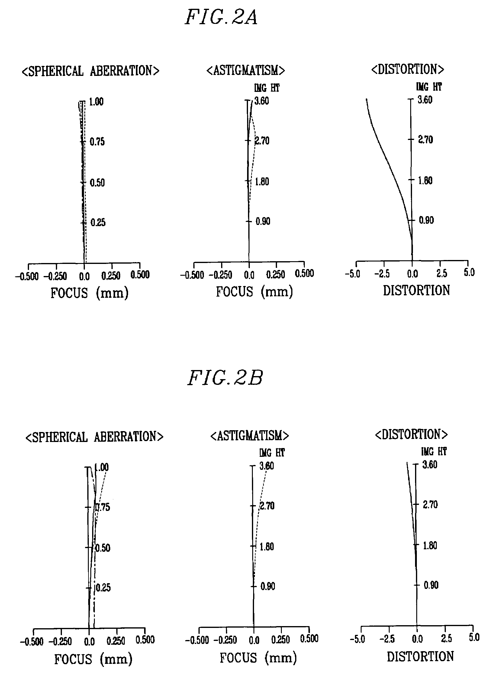
[0083]For the zoom lens the F-number Fno is in a range from about 2.84 to about 5.23 between the wide-angle position and the telephoto position, the focal length f is in a range from 5.99 to 17.30 mm, and the angle of view (2ω) is in a range from about 64.08° to about 23.78°. In the middle of the zoom lens, the F-number Fno is 4.10, the focal length f is 11.49 mm, and the angle of view (2ω) is 35.21°.
[0084]FIG. 3 illustrates the configuration of the zoom lens according to the second embodiment. The zoom lens according to the second embodiment has the same basic structure of the zoom lens according to the first embodiment, as illustrated in FIG. 3.
[0085]Various values associated with the component lenses of the zoom lens according to the second embodiment of the present invention are listed in Table 4.
[0086]
TABLE 4FaceThickness,RefractiveVarianceNumberRadius of Curvature (r)Distance (d)Index (nd)(v)*1250.000001.3000001.806140.74*25.409001.600000 38.749001.8600001.846723.78 424.28100...
PUM
 Abstract
Description
Claims
Application Information
 - R&D Engineer
- R&D Manager
- IP Professional
- Industry Leading Data Capabilities
- Powerful AI technology
- Patent DNA Extraction
Browse by: Latest US Patents, China's latest patents, Technical Efficacy Thesaurus, Application Domain, Technology Topic.
© 2024 PatSnap. All rights reserved.Legal|Privacy policy|Modern Slavery Act Transparency Statement|Sitemap