Zoom lens system

a zoom lens and zoom technology, applied in the field of zoom lens system, can solve the problems of image blurring, image deterioration, image blurring increase, etc., and achieve the effect of high zoom ratio and high zoom ratio

Active Publication Date: 2006-11-14
NIKON CORP
View PDF8 Cites 18 Cited by
  • Summary
  • Abstract
  • Description
  • Claims
  • Application Information

AI Technical Summary

Benefits of technology

[0020]The present invention is made in view of the aforementioned problems and has an object to provide a high zoom ratio zoom lens capable of shifting an image, which can carry out vibration reduction correction and accomplish a high zoom ratio.

Problems solved by technology

On the other hand, in particular for a compact and lightweight zoom lens, an image tends to be blurred during exposure by minute vibration produced on a camera while shooting such as a camera shake caused by a photographer upon releasing a shutter button.
When the amount of the camera vibration is assumed to be constant, the amount of image blurring increases in accordance with the increase in the focal length of the lens, so the minute camera vibration causes severe deterioration on the image.
Therefore, it is very difficult to combine to attain a high zoom ratio and to construct an optical system capable of shifting an image.
A conventional zoom lens having vibration reduction correction disclosed in Japanese Patent Application Laid-Open No. 2003-140048, however, has a large number of lens elements, and a vibration reduction mechanism has to be put into the lens barrel.
Accordingly, the total lens length and the diameter of the lens barrel become large, so the compactness tends to be spoiled.
Moreover, when the zoom lens is made to be a high zoom ratio with having a vibration reduction correction, deterioration in optical performance is severe, so that it becomes difficult to maintain sufficient optical performance as a zoom lens.
However, the driving mechanism for moving each lens group becomes complicated and the factors to produce mutual decentering of each lens group upon manufacturing increase, so that it becomes difficult to secure stable optical performance.

Method used


Image

  • Zoom lens system
  • Zoom lens system
  • Zoom lens system

Examples


first embodiment

[First Embodiment]

[0070]A zoom lens system according to a first embodiment of the present invention includes, in order from an object, a first lens group having positive refractive power, a second lens group having negative refractive power, a third lens group having positive refractive power, and a fourth lens group having positive refractive power. When the state of lens group positions varies from a wide-angle end state to a telephoto end state, the first lens group through the fourth lens group move such that a distance between the first lens group and the second lens group increases, a distance between the second lens group and the third lens group decreases, and a distance between the third lens group and the fourth lens group decreases. The third lens group includes at least two sub-lens groups having positive refractive power. The zoom lens system carries out vibration reduction correction by shifting an image by means of moving either sub-lens group of the two sub-lens grou...

example 1

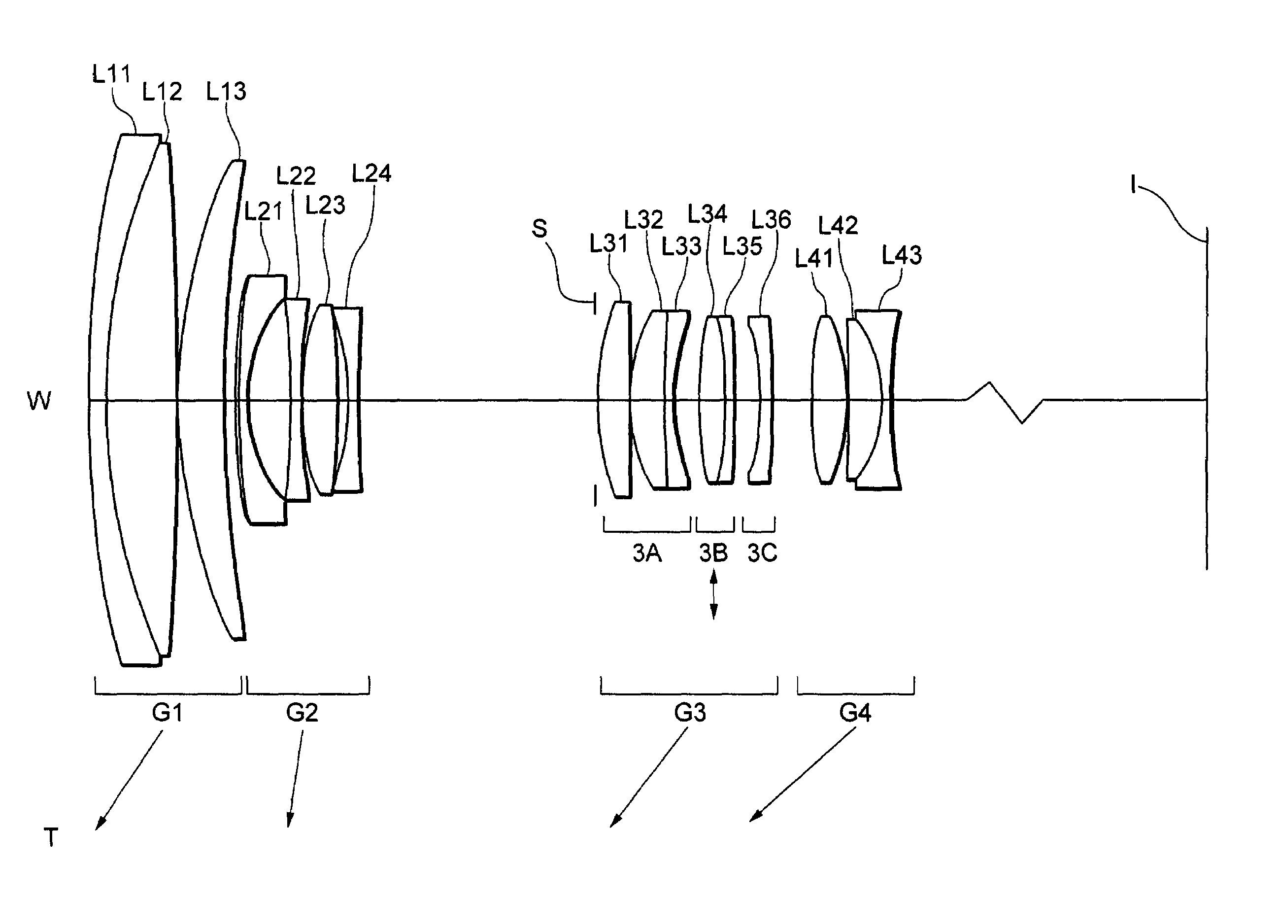
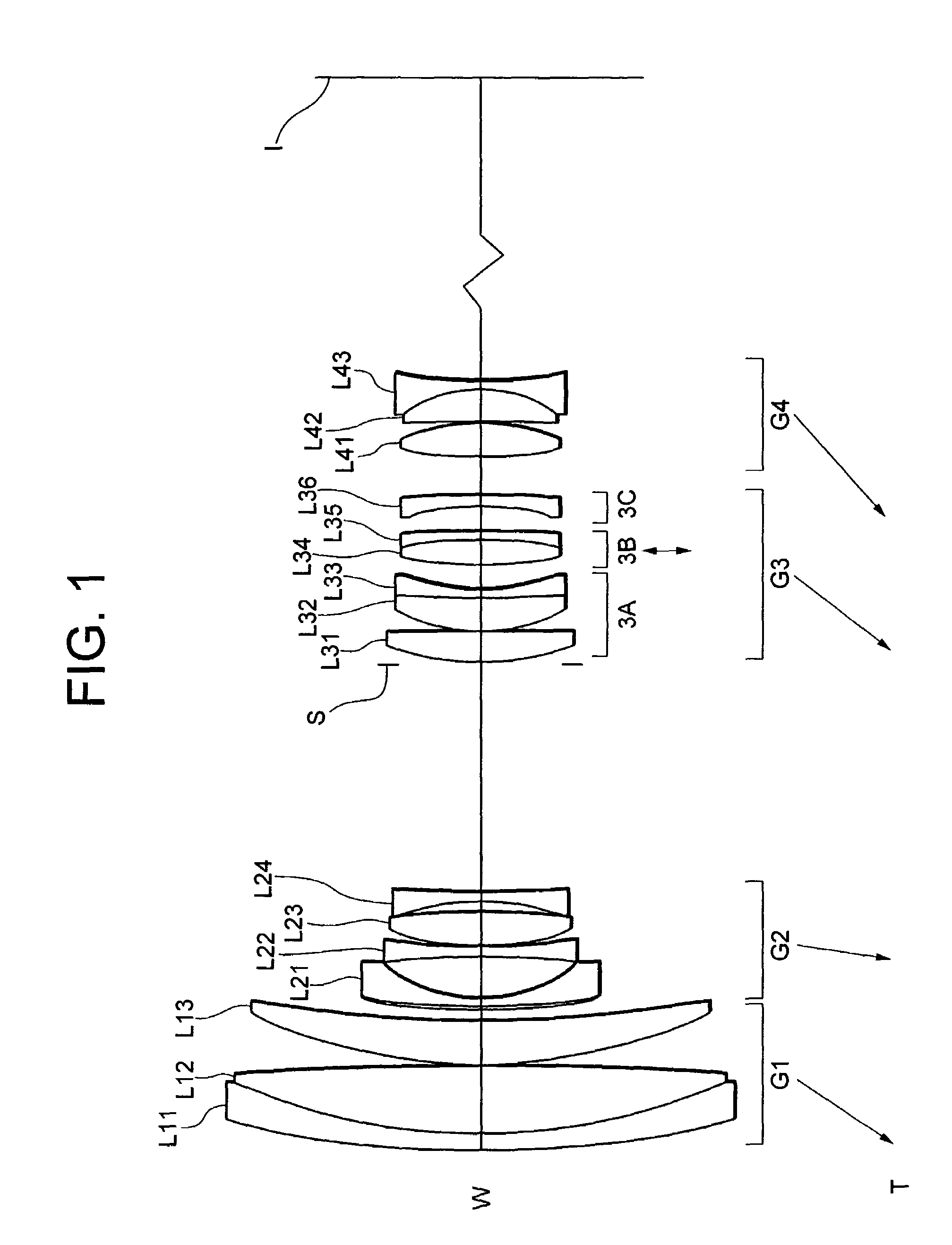
[0088]FIG. 1 is a diagram showing a sectional view of a zoom lens system according to Example 1 of the first embodiment of the present invention.

[0089]In FIG. 1, the zoom lens system is composed of, in order from an object, a first lens group G1 having positive refractive power, a second lens group G2 having negative refractive power, a third lens group G3 having positive refractive power, and a fourth lens group G4 having positive refractive power. When the state of lens group positions varies from a wide-angle end state to a telephoto end state, the first lens group G1 through the fourth lens group G4 move such that a distance between the first lens group G1 and the second lens group G2 increases, a distance between the second lens group G2 and the third lens group G3 decreases, and a distance between the third lens group G3 and the fourth lens group G4 decreases. The reference symbol I denotes the image plane.

[0090]The third lens group G3 is composed of, in order from the object,...

example 2

[0103]FIG. 5 is a diagram showing a sectional view of a zoom lens system according to Example 2 of the first embodiment of the present invention.

[0104]In FIG. 5, the zoom lens system is composed of, in order from an object, a first lens group G1 having positive refractive power, a second lens group G2 having negative refractive power, a third lens group G3 having positive refractive power, and a fourth lens group G4 having positive refractive power. When the state of lens group positions varies from a wide-angle end state to a telephoto end state, the first lens group G1 through the fourth lens group G4 move such that a distance between the first lens group G1 and the second lens group G2 increases, a distance between the second lens group G2 and the third lens group G3 decreases, and a distance between the third lens group G3 and the fourth lens group G4 decreases. The reference symbol I denotes the image plane.

[0105]The third lens group G3 is composed of, in order from the object,...


PUM


Abstract

A zoom lens system having high zoom ratio capable of shifting an image for vibration reduction correction. The system includes, in order from an object, a first lens group having positive power, a second lens group having negative power, a third lens group having positive power, and a fourth lens group having positive power. Each of the first lens group through the fourth lens group moves such that when zooming from a wide-angle end state to a telephoto end state, a distance between the first and the second lens groups increases, a distance between the second and the third lens groups decreases, and a distance between the third and the fourth lens group decreases. The third lens group includes at least two sub-lens groups having positive refractive power. Image shifting carried out by moving either of the two sub-lens groups perpendicularly to the optical axis. Given conditions are satisfied.

Description

[0001]The disclosures of the following priority applications are herein incorporated by reference:[0002]Japanese Patent Application No. 2003-051386 filed on Feb. 27, 2003; and[0003]Japanese Patent Application No. 2003-341903 filed on Sep. 30, 2003.BACKGROUND OF THE INVENTION[0004]1. Field of the Invention[0005]The present invention relates to a zoom lens system and in particular to a high zoom ratio zoom lens system capable of shifting an image.[0006]2. Related Background Art[0007]An optical system capable of moving (shifting) an image perpendicularly to the optical axis by moving (shifting) one or some of lens elements constructing the optical system substantially perpendicularly to the optical axis has been known. As for such optical systems, a zoom lens system capable of shifting an image by shifting one or some of lens elements provided in the zoom lens system has been proposed (see, for example, Japanese Patent Application Laid-Open No. 2003-140048 and Japanese Patent Applicati...

Claims


Application Information

Patent Timeline
Patent Type & Authority Patents(United States)
IPC IPC(8): G02B15/14G02B27/64G02B15/173
CPCG02B15/173G02B27/646G02B15/144113
Inventor ITO, TOMOKIOHTAKE, MOTOYUKI
Owner NIKON CORP
Why Eureka
Try Eureka