Zoom lens system and camera having same

a zoom lens and zoom technology, applied in the field of zoom lens system and camera, can solve the problems of unsuitable retractable structure, unfavorable compactness of photographing optical system whose refractive power is simply increased, and the complexity of the optical system, so as to achieve less variable optical performance and high zoom ratio

Inactive Publication Date: 2008-11-27
CANON KK
View PDF12 Cites 18 Cited by
  • Summary
  • Abstract
  • Description
  • Claims
  • Application Information

AI Technical Summary

Benefits of technology

[0014]The present invention provides a zoom lens system in which the magnification variation is more appropriately shared among lens units than in known zoom lenses so as to achieve a higher zoom ratio, and whose optical performance in use is less variable despite its retracting mechanism.

Problems solved by technology

In recent years, digital still cameras having a solid-state image pickup element have become increasingly sophisticated and small.
However, the zoom lenses disclosed in Japanese Patent Laid-Open Nos. 7-270684 and 11-305124, in which the second lens unit has almost all magnification variation functions, are unfit for the retractable structure because the first lens unit and the second lens unit are too sensitive to decentration.
However, a photographing optical system whose refractive power is simply increased is not as compact as expected because the lens thickness increases with the increase in refractive power.
In addition, compensation of aberrations becomes difficult.
When lens units of a camera not in use are retracted, errors such as inclination of lenses and lens units are inevitably large due to the mechanical structure.
If the lenses and the lens units are sensitive, the optical performance deteriorates and image shake occurs during zooming.

Method used


Image

  • Zoom lens system and camera having same
  • Zoom lens system and camera having same
  • Zoom lens system and camera having same

Examples


embodiment 2

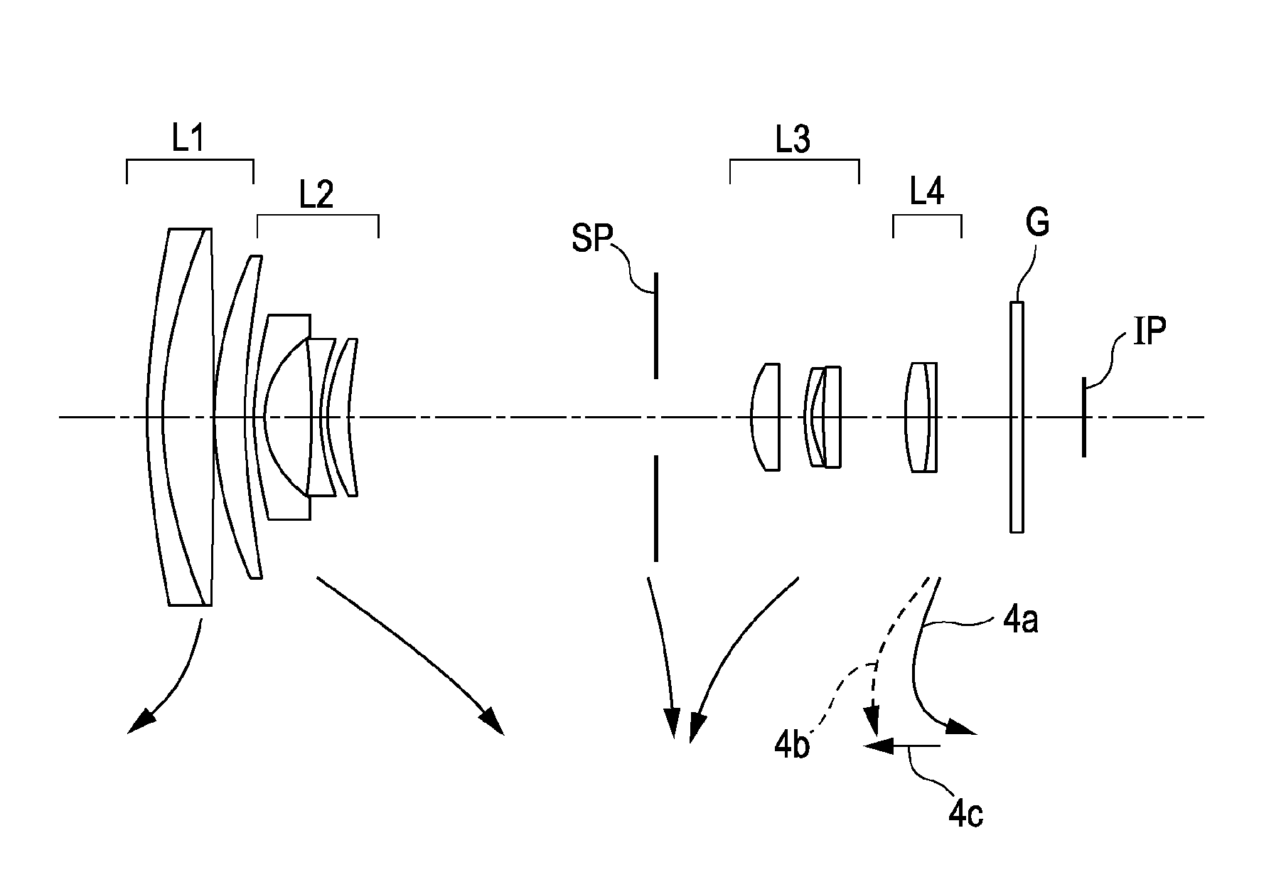
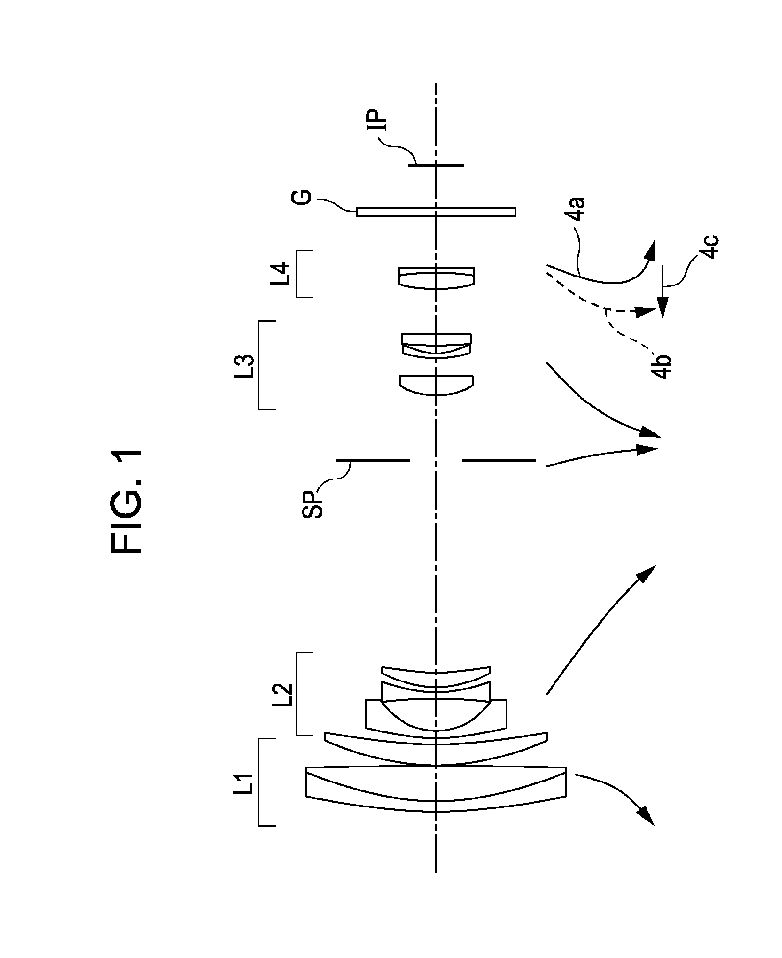
[0080]In Embodiment 2, the third lens unit L3 includes, in order from the object side to the image side, a positive lens element with a convex surface at the object side, a negative meniscus lens element with a convex surface at the object side, and a cemented lens consisting of a negative meniscus lens element with a convex surface at the object side and a positive lens element.

embodiment 3

[0081]In Embodiment 3, the third lens unit L3 includes, in order from the object side to the image side, a positive lens element with a convex surface at the object side, a negative meniscus lens element with a convex surface at the object side, and a cemented lens consisting of a biconvex positive lens element and a biconcave negative lens element.

[0082]The fourth lens unit L4 is a single positive lens element with a convex surface at the object side, or a cemented lens consisting of a positive lens element and a negative lens element.

[0083]The above-described lens configuration in each embodiment achieves a high-zoom-ratio yet being compact and a high-performance zoom lens.

[0084]In each embodiment, the above-described conditional expressions (1) and (2) are satisfied. More preferable conditions for solving various technical problems in a zoom lens will hereinafter be described.

[0085]The focal length fm is defined as:

fm=√(fw·ft),

where fw is the focal length of the zoom lens system ...


PUM


Abstract

A zoom lens system includes, in order from an object side to an image side, a first lens unit having positive optical power, a second lens unit having negative optical power, a third lens unit having positive optical power, and a fourth lens unit having positive optical power. Each lens unit moves during zooming. In particular, the first lens unit moves so as to be closer to an object at a telephoto end than at a wide-angle end during zooming, and the fourth lens unit moves in a locus convex toward the object side during zooming. The sharing of magnification variation between the third lens unit and the fourth lens unit is appropriately set.

Description

BACKGROUND OF THE INVENTION[0001]1. Field of the Invention[0002]The present invention relates to a zoom lens system and a camera having the same.[0003]2. Description of the Related Art[0004]In recent years, digital still cameras having a solid-state image pickup element have become increasingly sophisticated and small. Such cameras require, as a photographing optical system, a zoom lens that is compact yet has a high zoom ratio.[0005]There are known, as zoom lenses meeting such requirements, four-unit zoom lenses each including four lens units consisting of, in order from the object side to the image side, a first lens unit of positive refractive power, a second lens unit of negative refractive power, a third lens unit of positive refractive power, and a fourth lens unit of positive refractive power (Japanese Patent Laid-Open No. 7-270684 corresponding to U.S. Pat. No. 5,963,378, Japanese Patent Laid-Open No. 11-305124 corresponding to U.S. Pat. Nos. 6,166,864 and 6,751,028). In thi...

Claims


Application Information

Patent Timeline
Patent Type & Authority Applications(United States)
IPC IPC(8): G02B15/14
CPCG02B15/173G02B15/144113
Inventor SARUWATARI, HIROSHI
Owner CANON KK
Why Eureka
Try Eureka