Zoom lens, camera device, and data terminal device
a technology of camera device and zoom lens, applied in the field of zoom lens, camera device and data terminal device, can solve the problems of difficult shortening the time taken for focusing, difficult to reduce the weight and size of the third lens group, and difficult to increase the af speed without great driving power, and achieve the effect of high zoom ratio
- Summary
- Abstract
- Description
- Claims
- Application Information
AI Technical Summary
Benefits of technology
Problems solved by technology
Method used
Image
Examples
first embodiment
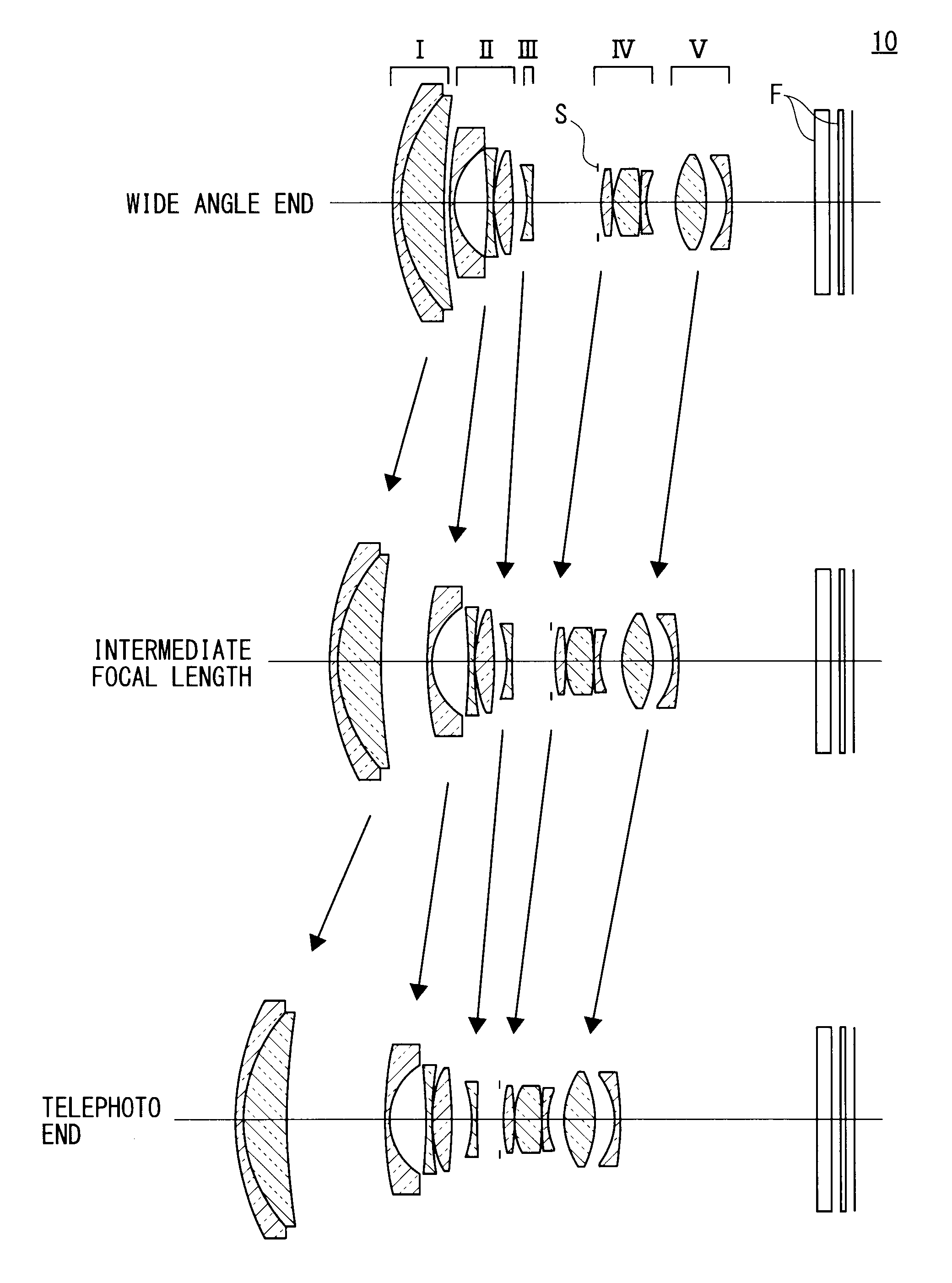
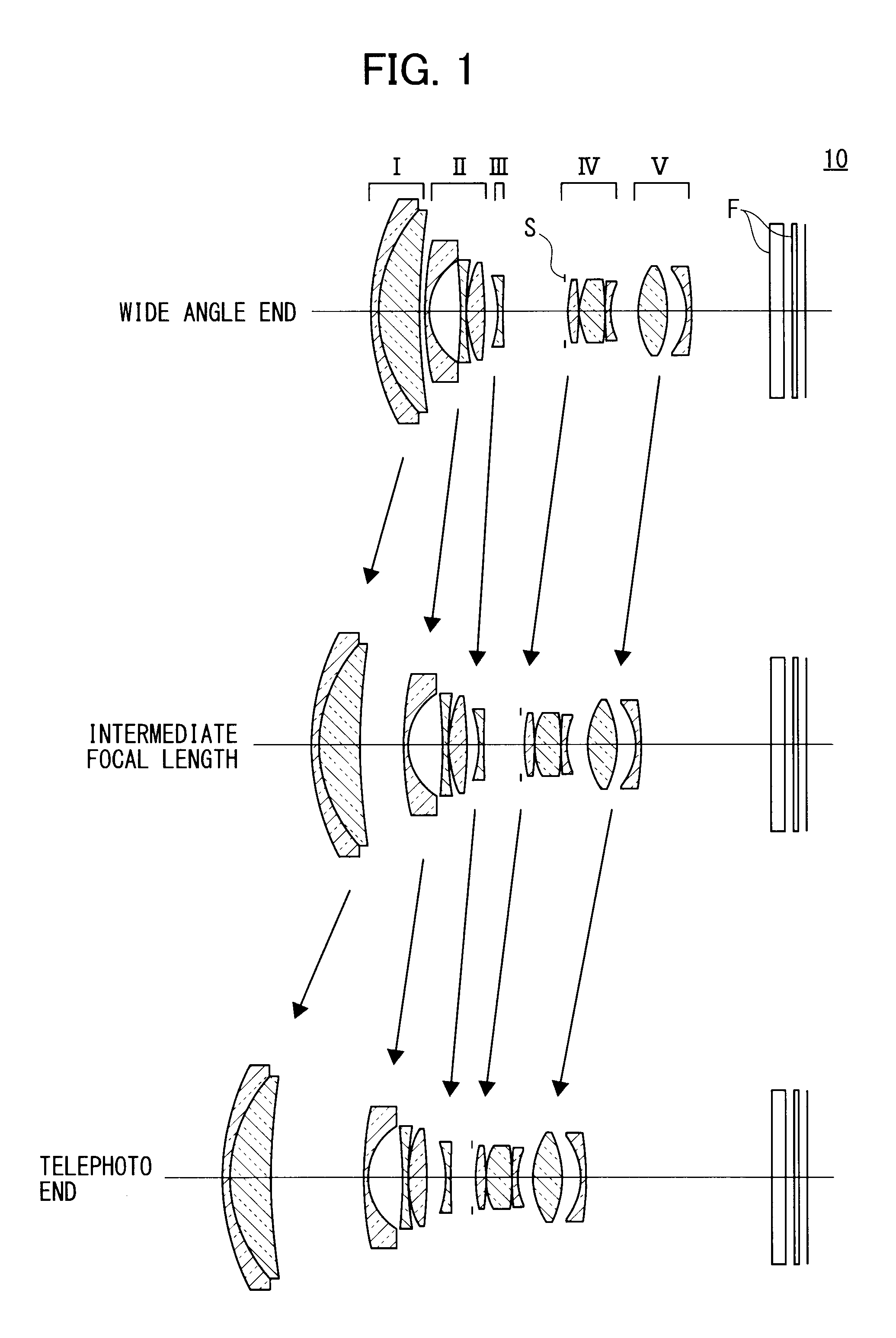
[0089]The following table 1 shows specific data on the zoom lens 10 in FIG. 1 with f=15.99 to 46.53, F=3.66 to 5.81, and ω=41.8 to 17.08.
TABLE 1GlassFace No.rdndvdθ gFMaterialR139.122731.21.9228618.90.6495SNPH2OHARAR223.282336.878241.88340.760.5667SLAH58OHARAR3124.3126Variable AR4*51.185760.91.9027310.5943LLAH86OHARAR59.804715.13832R6−53.77860.91.88340.760.5667SLAH58OHARAR740.91710.1R817.435333.084781.9228618.90.6495SNPH2OHARAR9−49.33344Variable BR10−19.123510.91.88340.760.5667SLAH58OHARAR1199.43789Variable CR12∞0.4R13*20.923181.783931.5891361.150.5382LBAL35OHARAR14−40.367730.1R1511.557044.213751.49781.540.5375SFPL51OHARAR16−39.616420.1R17223.61790.91.9036631.320.5947TAFD25HOYAR1812.13573Variable DR1913.214774.801381.5182358.90.5457SNSL3OHARAR20−16.478213.08285R21*−10.35970.91.86440.580.5669LLAH83OHARAR22*−25.28317ArbitraryR23∞2.31.516864.2FiltersR24∞1.5R25∞0.71.516864.2Cover GlassR26∞
[0090]Specific data on the aspheric surfaces of the zoom lens 10 according to the first embodiment ...
second embodiment
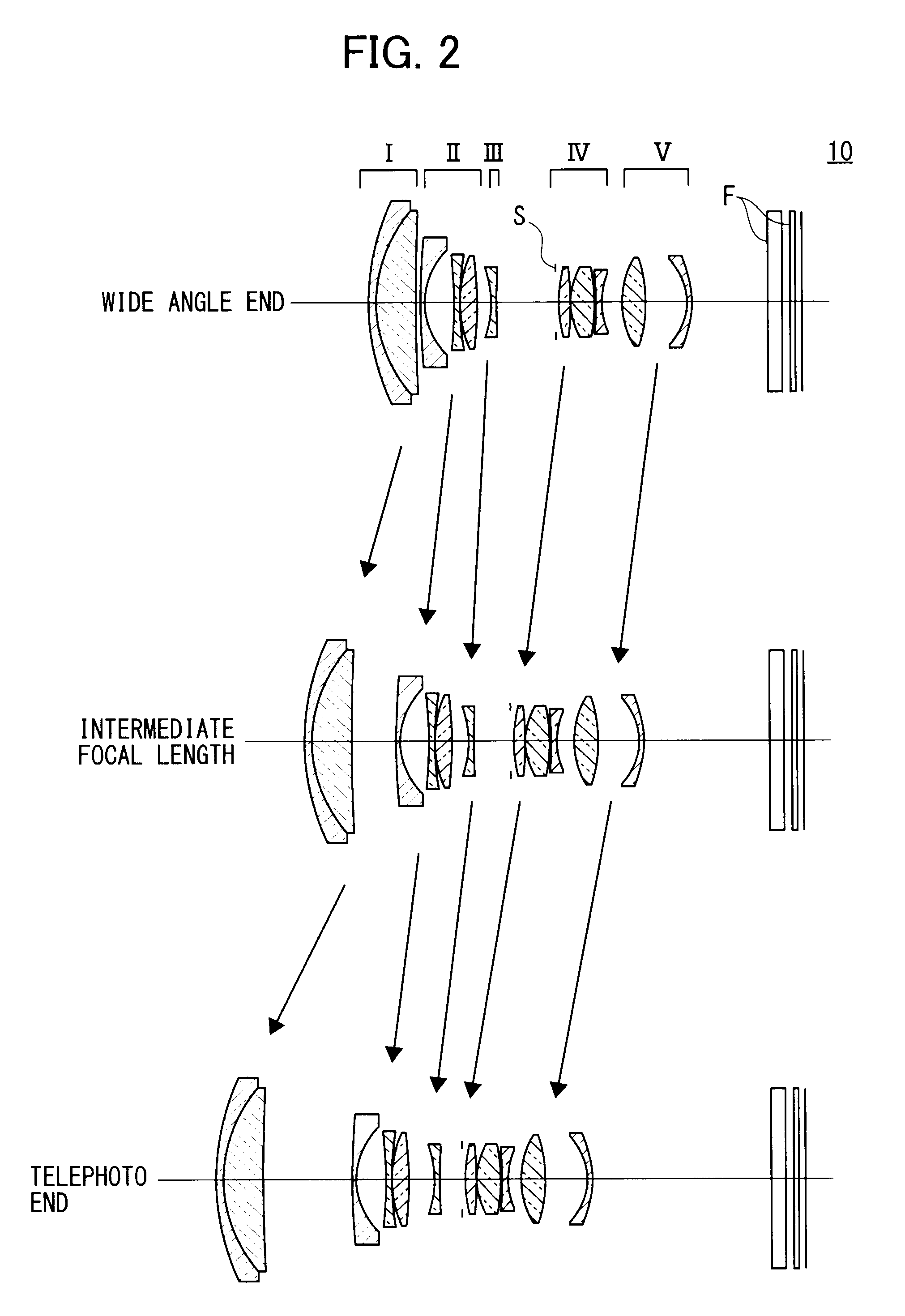
[0111]The following table 3 shows specific data on the zoom lens 10 in FIG. 2 with f=18.65 to 54.3, F=3.62 to 5.83, and ω=37.5 to 14.8.
TABLE 3GlassFace No.rdndvdθ gFMaterialR134.875291.21.9228618.90.6495SNPH2OHARAR220.880976.48641.76240.10.5765SLAM55OHARAR3274.4841Variable AR4*83.171040.91.9027310.5943LLAH86OHARAR511.041464.70677R6−71.072260.91.88340.760.5667SLAH58OHARAR735.277540.1R817.301522.795331.9228618.90.6495SNPH2OHARAR9−47.57628Variable BR10−16.61780.91.88340.760.5667SLAH58OHARAR11392.0196Variable CR12∞0.4R13*25.283091.869041.5891361.150.5382LBAL35OHARAR14−33.489110.1R1511.134124.027711.49781.540.5375SFPL51OHARAR16−21.681790.1R17−50.303850.91.9036631.320.5947TAFD25HOYAR1812.84878Variable DR1914.16973.923131.5407247.230.5651STIL2OHARAR20−20.884846.7438R21*−9.130290.91.86440.580.5669LLAH83OHARAR22*−17.25279ArbitraryR23∞2.31.516864.2FiltersR24∞1.5R25∞0.71.516864.2Cover GlassR26∞
[0112]Specific data on the aspheric surfaces of the zoom lens 10 according to the second embodiment a...
third embodiment
[0133]The following table 5 shows specific data on the zoom lens 10 in FIG. 3 with f=16.15 to 38.0, F=3.63 to 5.86, and ω=41.5 to 20.6.
TABLE 5GlassFace No.rdndvdθ gFMaterialR147.760351.21.9228618.90.6495SNPH2OHARAR226.407144.140711.88340.760.5667SLAH58OHARAR3157.9338Variable AR4*317.05930.91.9027310.5943LLAH86OHARAR511.330164.09559R6−32.40710.91.88340.760.5667SLAH58OHARAR7−147.8840.1R818.63362.624631.9228618.90.6495SNPH2OHARAR9−54.59411Variable BR10−15.17690.91.88340.760.5667SLAH58OHARAR11116.3303Variable CR12∞0.4R13*21.569151.812611.5891361.150.5382LBAL35OHARAR14−35.006740.1R1511.548052.268641.49781.540.5375SFPL51OHARAR16−62.396830.1R1784.207761.245521.9036631.320.5947TAFD25HOYAR1815.65855Variable DR1919.021323.048761.49781.540.5375SFPL51OHARAR20−19.882863.40451R21*−20.708430.91.86440.580.5669LLAH83OHARAR22*−930.2132ArbitraryR23∞2.31.516864.2FiltersR24∞1.5R25∞0.71.516864.2Cover GlassR26∞
[0134]Specific data on the aspheric surfaces of the zoom lens 10 according to the third embodime...
PUM
 Abstract
Description
Claims
Application Information
 - R&D
- Intellectual Property
- Life Sciences
- Materials
- Tech Scout
- Unparalleled Data Quality
- Higher Quality Content
- 60% Fewer Hallucinations
Browse by: Latest US Patents, China's latest patents, Technical Efficacy Thesaurus, Application Domain, Technology Topic, Popular Technical Reports.
© 2025 PatSnap. All rights reserved.Legal|Privacy policy|Modern Slavery Act Transparency Statement|Sitemap|About US| Contact US: help@patsnap.com


