Tool pack assembly

a tool pack and tool technology, applied in the field of tool pack assembly, can solve the problems of loss of production and efficiency, manufacturing and quality problems, etc., and achieve the effects of preventing tear off and remelting, improving dampening means, and facilitating passage through die elements

Active Publication Date: 2006-09-19
PRIDE ENG LLC
View PDF8 Cites 9 Cited by
  • Summary
  • Abstract
  • Description
  • Claims
  • Application Information

AI Technical Summary

Benefits of technology

[0008]A tool pack assembly may be comprised of various combinations of components including redraw die assemblies, single or double die assemblies, spacer devices and / or coolant spacer devices, for example, depending on size restraints or requirements and the desired process or effect on the can body. For example, the tool pack assembly of the invention may be comprised of a redraw die retainer, a redraw die carrier, a first single die module, a spacer member, a second single die module, a second spacer member, a coolant spacer member, and a third single die module. The tool pack elements form a housing area to hold die assemblies used for thinning the sides of a metal can. A die assembly may be comprised of a die ring and a die element, for example. Coolant / lubricant apertures are in communication with the housing to provide coolant to the metal body being formed. When metal can bodies are rammed or punched through the tool pack and body maker, heat is produced. If a can body becomes improperly centered and / or is too hot in a body maker, manufacturing and quality problems occur, i.e. tear-off and remelt. These problems may result in the shut down of the body maker to retrieve the damaged object(s), which results in a loss of production and efficiency. Thus, it is an advantage of the present invention to provide a tool pack assembly which minimizes production and quality problems.
[0009]The present invention provides a die module having improved dampening means. The die module may be a single or a double die module. The die module is a generally circular annular structure, and which forms a housing for a die ring and die element through which can bodies pass. The upstream side of the die module may contain a lube ring which is in communication with coolant / lube apertures and which serves to evenly provide lube / coolant to a can body to ease passage through a die element and prevent tear off and remelt. The downstream side of the die module receives the die assembly and includes a plurality of formed cavities having angular openings for receiving spring means to bias or float a die element to thereby permit proper alignment of the can body with the die element. Air channels are provided on the upstream surface of the die housing and are in communication with air inlet apertures contained in the tool pack assembly. Because a die assembly has a tendency to stick to the die module housing when a metal body is punched through the tool pack and body maker, the air flow in the channels forces the die assembly from the module surface and into a floating, recentered position.
[0010]Importantly, improved dampening means are provided for radial positioning of the die assembly in the die module housing. The dampening means comprises a spring means and a cooperating rigid contact body or pin member both having specified configurations. The spring means are preferably constructed of an elastomeric material, i.e., urethane or a like elastomeric compressible polymeric or other material having similar memory and dampening effects as urethane. The spring means may also be provided in a coil spring configuration or the like. The contact or pin members are preferably of a predetermined generally trapezoidal configuration which provide increased wear surfaces and are constructed of tool steel or a like hard and durable material. The spring means are constructed and arranged to cooperate with the pin or contact members to form the dampening means to bias or float the die element. Preferably the spring and contact members are interconnected to provide a joined structure.
[0011]It is an advantage of the present invention to provide a tool pack assembly capable of high cyclic operation, i.e. 500 cans per minute. It is a further advantage of the present invention to prevent damage to the can bodies during manufacture, i.e. tear-off and remelt, due to the use of the improved dampening means in the die module.
[0012]It is a benefit of the present invention to provide an improved die module which reliably and properly aligns a metal body driven by the body maker punch with an ironing die; i.e. by floating the die and by providing guiding means to center the metal body. It is a further benefit of the present invention to float the die using an elastomeric spring means which is durable and easily monitored and replaced. It is a further benefit of the present invention to provide a dampening means having a contact member which provides a relatively large wear surface.
[0013]These and other benefits and advantages of this invention will become clear from the following description by reference to the drawings.

Problems solved by technology

If a can body becomes improperly centered and / or is too hot in a body maker, manufacturing and quality problems occur, i.e. tear-off and remelt.
These problems may result in the shut down of the body maker to retrieve the damaged object(s), which results in a loss of production and efficiency.

Method used


Image

  • Tool pack assembly
  • Tool pack assembly
  • Tool pack assembly

Examples


Embodiment Construction

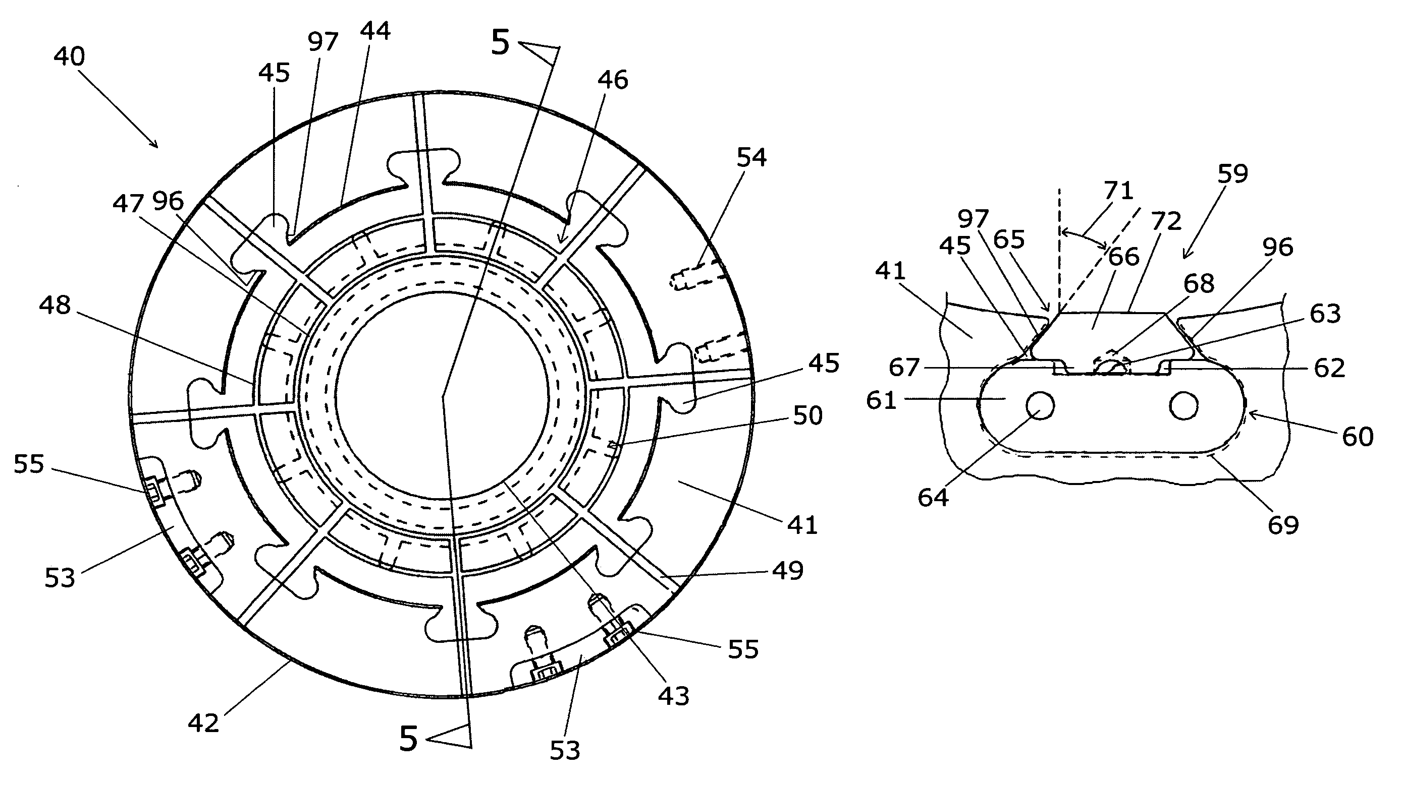
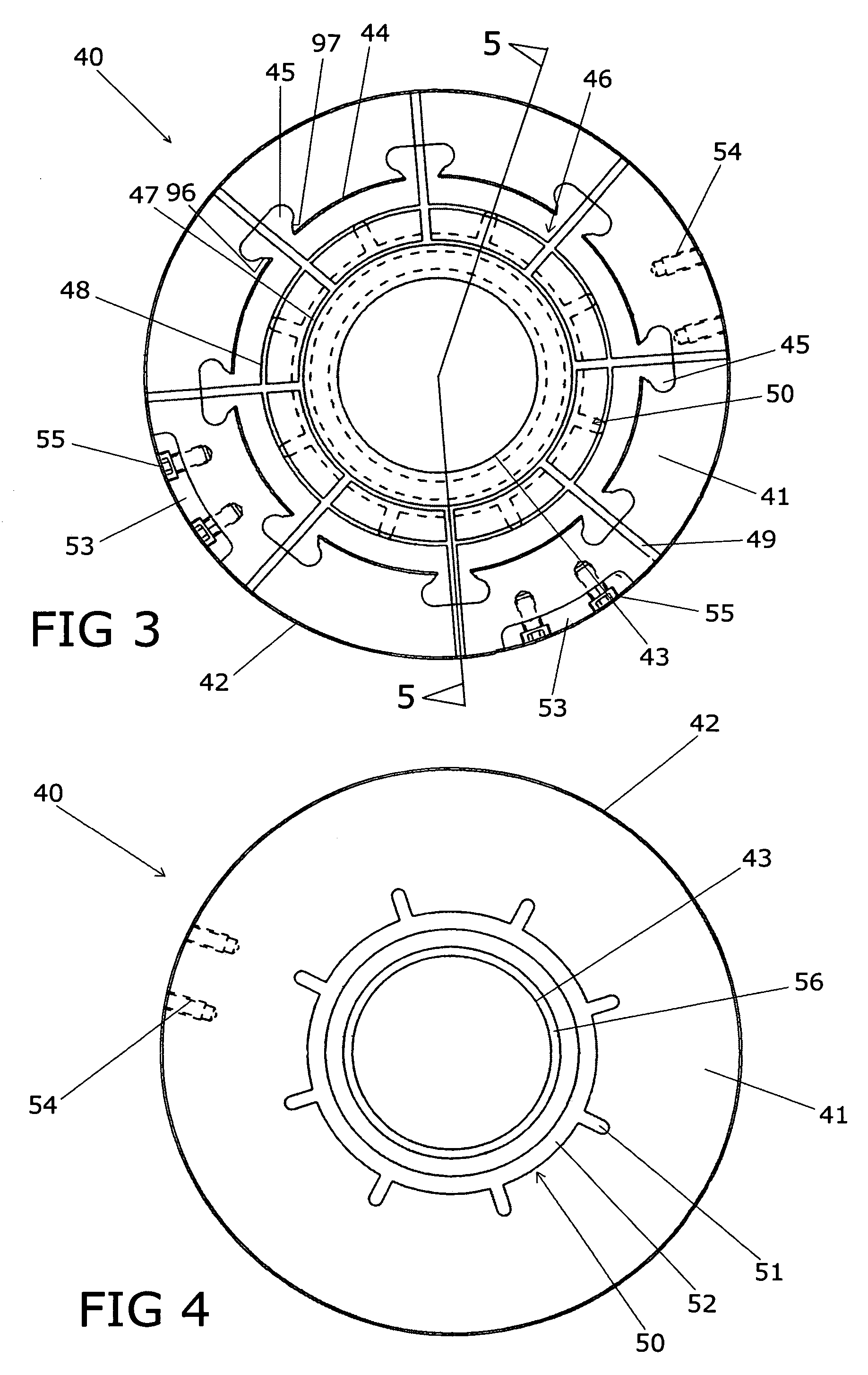
[0026]The tool pack assembly of the present invention is constructed and arranged for use in the drawing and ironing of bodies for two piece metal cans. The tool pack assembly of the present invention is constructed and arranged for use in a body maker assembly for the manufacture of two piece can bodies. The tool pack assembly of the present invention is constructed to contain die elements to form the body parts of two piece metal cans and which further includes an improved single or double die module having improved dampening means. Although tool pack assemblies may comprise various configurations having various cooperating elements, an exemplary tool pack assembly 10 is discussed herein.

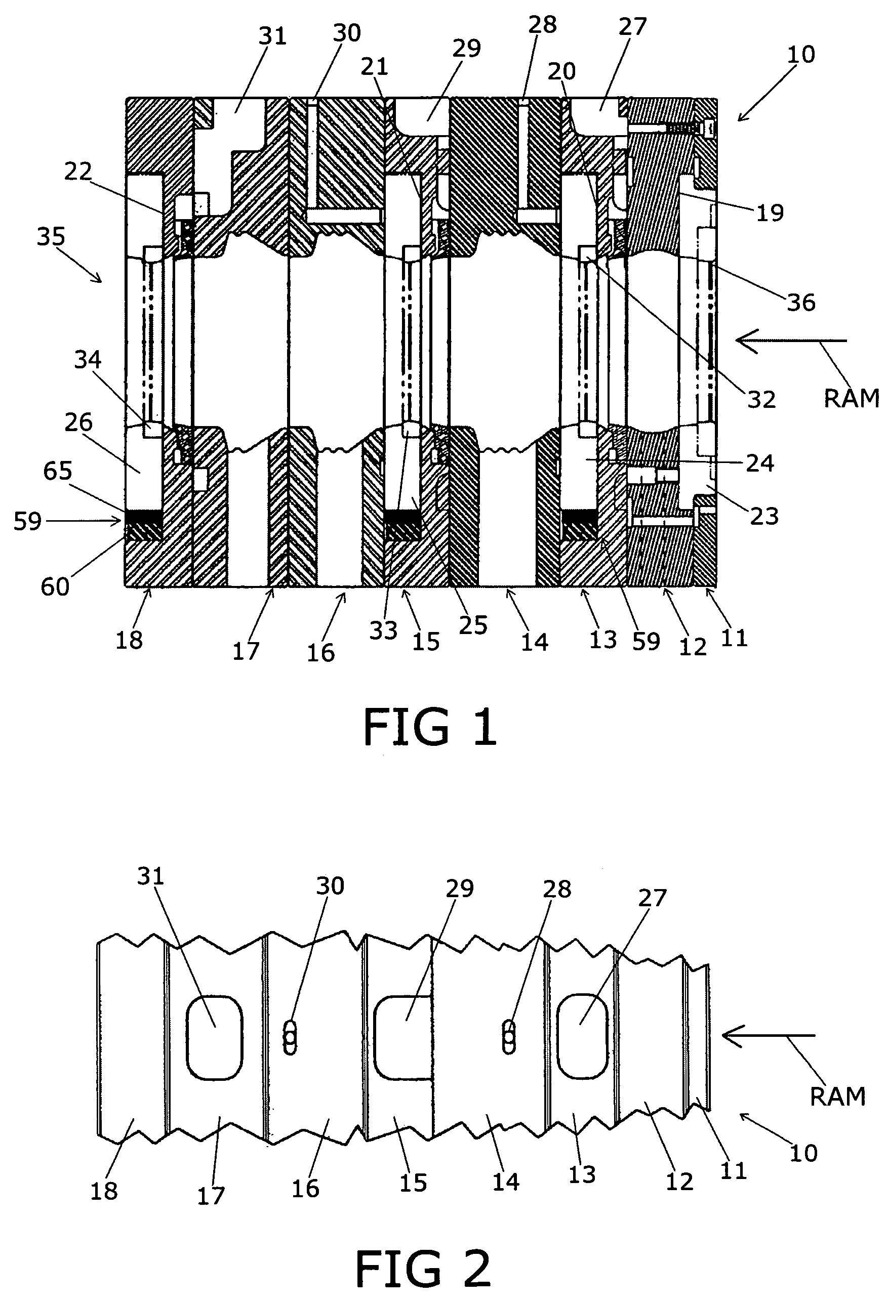
[0027]FIG. 1 shows tool pack assembly 10 being comprised of redraw die retainer 11, redraw die carrier 12, single die module 13, spacer member 14, single die module 15, spacer member 16, coolant spacer member 17 and single die module 18. Internal housing area 35 is shown defined by elements 11–18 ...


PUM

PropertyMeasurementUnit
angleaaaaaaaaaa
angleaaaaaaaaaa
angleaaaaaaaaaa

Abstract

A tool pack assembly for use in the manufacture of two piece metal can bodies. The tool pack assembly of the present invention is constructed and arranged for use in a body maker assembly to form parts of metal cans. The tool pack assembly of the invention includes an improved die module structure. The improved die module includes compressible dampening structures to thereby float a die element to center and align the metal body with the die element.

Description

[0001]This Application claims the benefit of U.S. Provisional Patent Application Ser. No. 60 / 619,477, filed on or about Oct. 15, 2004.BACKGROUND OF THE INVENTION[0002]The present invention relates generally to ironing mechanisms for use in the manufacture of metal containers. Particularly, the invention relates to a tool pack assembly used in the drawing and ironing of bodies for two piece steel and aluminum cans. More particularly, the invention relates to improved floating die module assemblies for use in a tool pack assembly for the manufacture of metal containers.[0003]The tool pack assembly of the present invention is an improvement of the tool pack assembly disclosed in U.S. Pat. No. 4,554,815 ('815 Patent) to Weishalla, entitled Tool Pack Assembly and assigned to the assignee of Applicant's present Application. The tool pack assembly of the '815 Patent, incorporated by reference herein, utilizes floating ironing and guiding dies which axially realign within the internal housi...

Claims


Application Information

Patent Timeline
Patent Type & Authority Patents(United States)
IPC IPC(8): B21D22/00
CPCB21D22/21B21D22/283B21D22/28
Inventor ZAUHAR, MARK L.
Owner PRIDE ENG LLC
Why Eureka
Try Eureka