Light pollution shield

a technology of light pollution and shields, applied in outdoor lighting, fixed installation, lighting and heating equipment, etc., can solve the problems of shields being moved inadvertently from their set position, rotatable shields, and irritants from spilling over lighting, etc., to achieve convenient installation and easy adjustment

Inactive Publication Date: 2007-09-04
CORDELIA LIGHTING
View PDF11 Cites 35 Cited by
  • Summary
  • Abstract
  • Description
  • Claims
  • Application Information

AI Technical Summary

Benefits of technology

[0007]The present invention is directed to providing a lighting system that is easy to install, and which provides the installer with the option of customizing the illuminated field or light pattern by selectively blocking the light cast by the light source. Thus, the direction, pattern and general intensity of illumination can be custom tailored in the field by the end user to suit the immediate needs of the location where the light is installed. Additionally, once the lighting system is installed and customized to project light of a desired shape, the invention is configured not to allow the shape of the emitted light to be accidentally altered, or to be altered by wind or vibration forces. Further, the size and shape of the light blocking shield is easily adjusted by the end user in the field.

Problems solved by technology

In the close quarters of some metropolitan areas, such spill over lighting is an irritant, especially if the light illuminates the interior of a neighbor's bedroom during sleeping hours.
However, a rotatable shield has several disadvantages.
One disadvantage is that the shield may be inadvertently moved from its set position by forces such as wind or physical vibration of the supporting structure.
Another disadvantage is that shield and attachment hardware are difficult to fabricate and not easily adjusted to precisely block light.
Yet another disadvantage is that the shield has a prefabricated shape that is determined during manufacture.
Such a predetermined shape does not permit exact tailoring in the field by the consumer to fit the myriad of lighting applications.
Thus, such a rotatable shield does not enable the installer or homeowner to truly customize the light pattern by selective blocking the light emission.

Method used


Image

  • Light pollution shield
  • Light pollution shield
  • Light pollution shield

Examples


Embodiment Construction

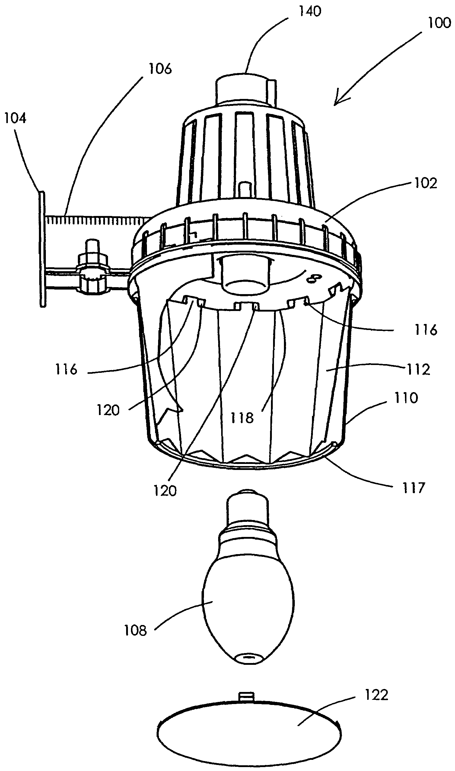
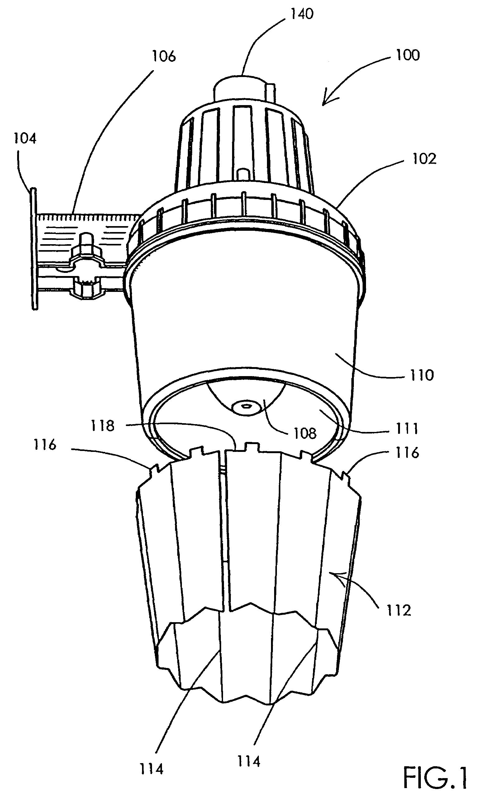
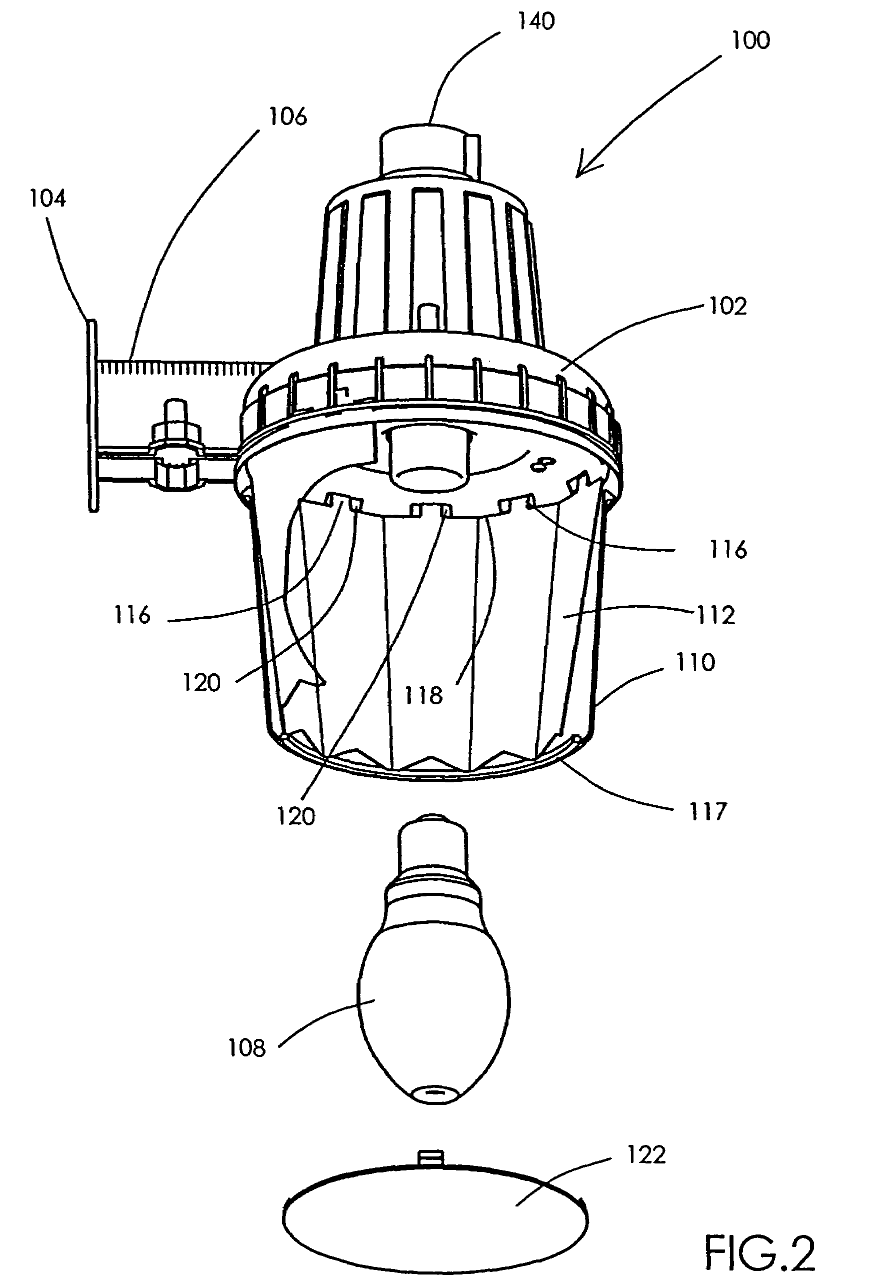
[0014]As shown in the drawing figures, which are provided for purposes of exemplary illustration, the present invention is directed to a lighting system 100. The lighting system 100 benefits from a highly customizable light blocking shield to control light pollution.

[0015]Referring to FIGS. 1-2, forming the central portion of the lighting system 100 is a housing 102 preferably made of a metal such cast iron, steel, aluminum, plastic, or the like. A vertical mounting plate 104 is indirectly attached to or extends from the housing 102 via a horizontal suspension arm 106. The vertical mounting plate 104 is configured to connect the housing 102 to a wall, post, or other permanent support structure. The housing 102 is designed to receive a light source 108, such as an incandescent bulb, neon tube, fluorescent tube, halogen bulb, mercury-vapor element, LED cluster, or the like, which is connected to an AC power supply in the conventional way. The AC power supply is of course optional sinc...


PUM


Abstract

A lighting system producing a light pattern that is customized in the field by the end user to minimize light pollution. A housing supports a light source that is connected to a power supply. The housing defines an interior chamber. An opaque or low visible light transmissivity shield is bent or formed into a generally tubular shape and is inserted into the chamber surrounding the light source. The shield includes folds, perforations, pre-scoring, grooves, and the like defining sections that can be easily detached to create windows. The windows permit outgoing light to pass while the remaining areas of the shield attenuate or block the outgoing light. The shield includes teeth that engage respective recesses in the housing to prevent rotation of the shield once installed.

Description

FIELD OF THE INVENTION[0001]The present invention relates generally to outdoor lighting systems, and in particular, to improved aspects of such lighting systems for directing the light beam that emits from the lighting system.BACKGROUND OF THE INVENTION[0002]It is common to erect exterior lighting around domestic, industrial, or military property to provide security against intruders, and to provide lighting for visitors and authorized personnel. The need frequently arises for the lighting system to provide a “customized” light pattern, in which a beam of light is desired to be cast in one specific direction, but not in other directions.[0003]In a domestic or residential application where it is common for homes to be built close to each other, the outdoor lighting of one home might project light into a neighbor's home. In the close quarters of some metropolitan areas, such spill over lighting is an irritant, especially if the light illuminates the interior of a neighbor's bedroom du...

Claims


Application Information

Patent Timeline
Patent Type & Authority Patents(United States)
IPC IPC(8): F21V1/06
CPCF21V11/16F21V9/08F21V17/10F21W2131/10
Inventor MONROE, TIM E.WANDREY, JOHN H.
Owner CORDELIA LIGHTING
Why Eureka
Try Eureka