
Pressure processing apparatus with improved heating and closure system

a technology of processing apparatus and sealing system, which is applied in the direction of lighting and heating apparatus, cleaning using liquids, transportation and packaging, etc., can solve the problems of affecting the production of integrated circuits with very fine, high-density circuit patterns, and pattern collapse, etc., to achieve the effect of reducing the number of parts

Active Publication Date: 2004-06-24
HANSEN BRIAN
View PDF9 Cites 4 Cited by
  • Summary
  • Abstract
  • Description
  • Claims
  • Application Information

AI Technical Summary

Benefits of technology

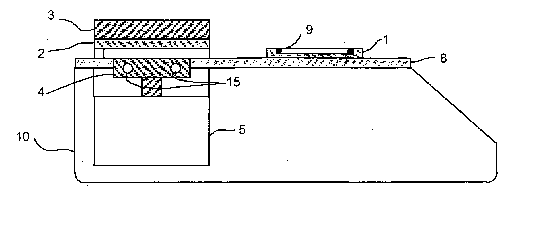
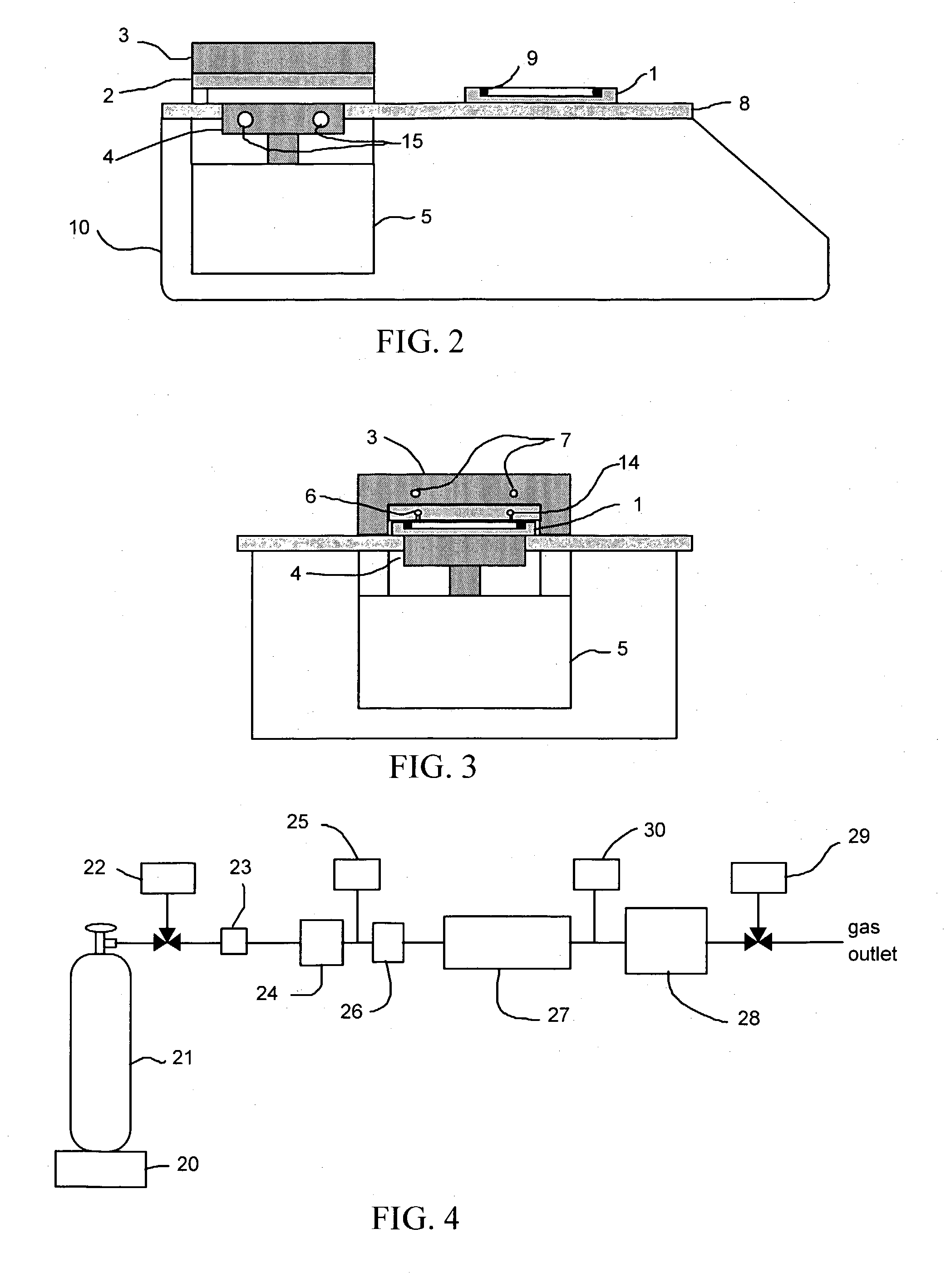
[0022] (a) The pressure chamber design decreases particulate contamination production during both operational and maintenance procedures, facilitating installation of the invention within clean room environments and allowing decreased workpiece failure rates. Because it is simply a part of the removable stage, the primary maintenance item of the pressure chamber apparatus, the sealing means (such as a plastic, elastic, or metallic o-ring), can be easily and cleanly replaced without opening or dismantling any additional parts of the apparatus and without moving the bulk of the apparatus out of the clean room environment.
[0023] (b) Because the chamber top is fixed and heated, the cycle time for cleaning and / or drying a workpiece is much shorter than if the cover were removable and unheated. The heated chamber top (3) facilitates thermal equilibration of the processing gas or fluid within the chamber.
[0025] (d) The apparatus has only a small number of moving parts, and except for the top of the push plate (4), they are all contained within the housing (10). This minimizes the production and release of harmful particulates.
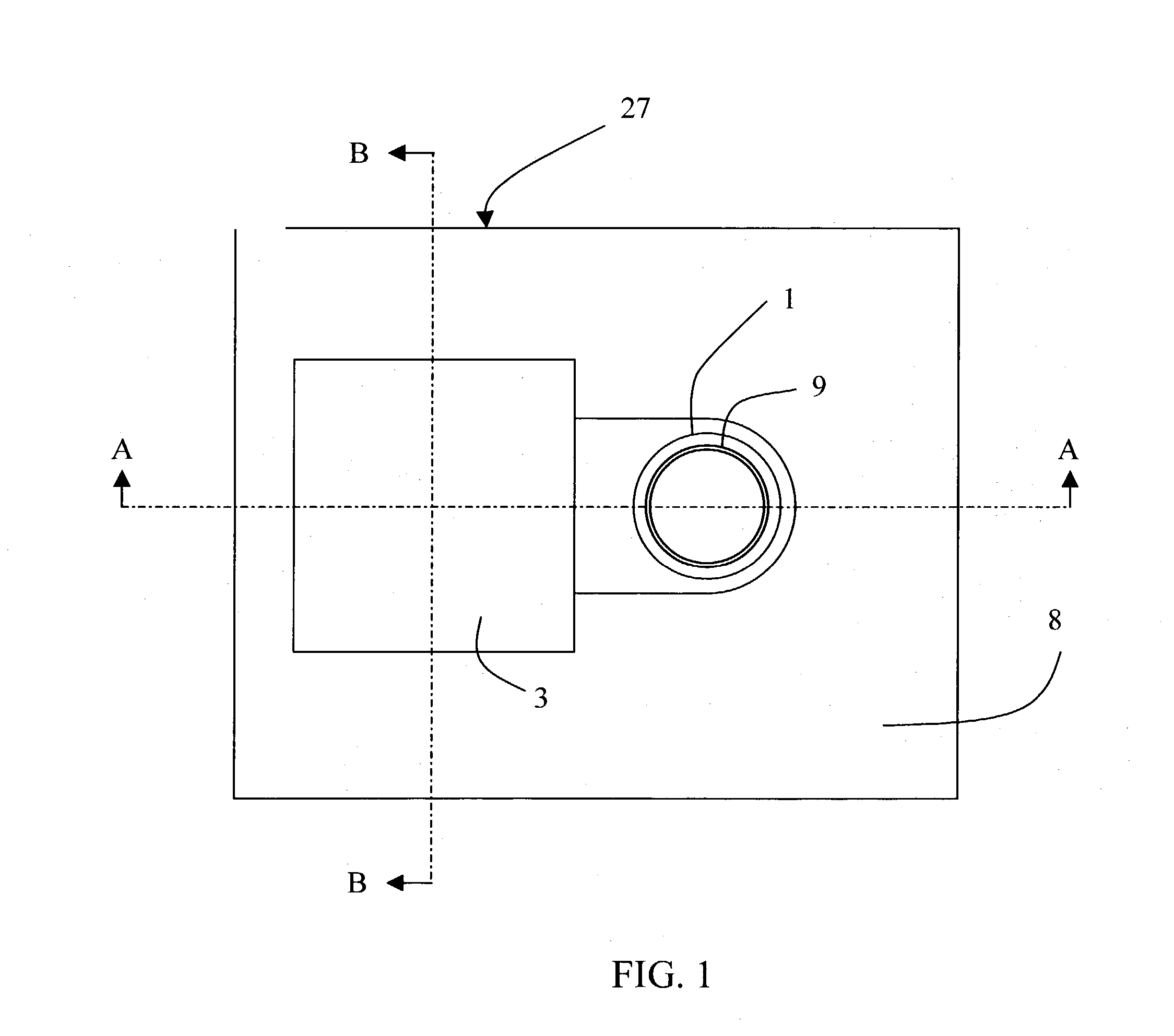
[0026] In order to solve the problems described above, an object of the present invention is to allow clean operation and maintenance of the apparatus for processing workpieces with a gas or fluid under temperature and pressure control using a chamber which has two portions, one of which is removable and acts as a stage on which workpieces can be mounted and which has the sealing means attached to it, allowing easy and clean replacement of the sealing means, said chamber being closed by pressing the two portions together. Further, the moving parts of the pressing means are contained within a housing. Another object of the present invention is to facilitate rapid operation for processing workpieces by maintaining the top and bottom of the chamber at chosen temperature and by preheating the fluid prior to its entrance into the chamber. In short, the present invention offers significant and novel advantages in its design and operation largely related to its cleanliness, temperature control, and ease of loading and unloading.

Problems solved by technology

The production of integrated circuits with very fine, high-density circuit patterns, for example with pattern widths of less than 100 nm, is hindered by the difficulty of wetting the surfaces of the features during production and wash steps.
Furthermore, surface tension and related capillary effects can cause pattern collapse during the drying of very fine IC devices.
A related problem caused by surface tension effects has long been recognized in the production of MEMS devices (Jafri, Moritz, Busta, & Walsh, 1999; Maboudian & Howe, 1997; Mulhern, Soane, & Howe, 1993).
As the water evaporates during the drying process, its high surface tension causes it to pull at the delicate features, breaking them or sticking them to the surface (the so-called "stiction" problem).
Due to the near-zero surface tension of the fluid, supercritical carbon dioxide processing method for drying ultrafine IC or MEMS devices is gentler on the surface features than other (wet) methods, potentially lowering the failure rate of manufactured devices (Jafri et al., 1999).
The problem with such particulates is that that they lead to higher failure rates of processed workpieces.
Existing devices for processing workpieces under gases or fluids under temperature and pressure control have significant operational and / or maintenance problems with respect to particulate generation and workpiece and / or workroom contamination.

Method used


Image

  • Pressure processing apparatus with improved heating and closure system
  • Pressure processing apparatus with improved heating and closure system
  • Pressure processing apparatus with improved heating and closure system

Examples


Embodiment Construction

[0033] A preferred embodiment of the invention is depicted in FIGS. 1-5 and will be described below in reference to the Figures. To facilitate clarity in the description of crucial aspects of the invention, well-known components, circuits, manifolds, and procedures are not described in detail. The invention can, of course, take the form of additional embodiments, so the preferred embodiment that is described is intended to describe and teach the invention without limiting the specific details of the invention. For example, the invention can be oriented so that the chamber opens and closes in a horizontal instead of vertical direction. One of ordinary skill in the art will be able to envision and practice the invention as described or in related, alternative embodiments.

[0034] The present invention includes a removable stage 1 upon which are positioned one or more workpieces to be processed. The stage 1 is moved in the axial direction of the chamber by the push plate 4, which is driv...


PUM

PropertyMeasurementUnit
Temperatureaaaaaaaaaa
Pressureaaaaaaaaaa

Abstract

Apparatus for pressure processing components is disclosed which includes an improved closure system that minimizes dust-generating parts and allows easy access to the chamber. Ports are provided for introducing and releasing pressurized gases and fluids to and from the processing space. The heating system of the apparatus heats both the cover and the stage inside the pressurized chamber such that cycle time to equilibrate heated, pressurized fluids such as supercritical carbon dioxide inside the chamber are decreased. The apparatus includes a mechanism that raises the stage inside the chamber, pressing it against the fixed cover and sealing the inside of the pressure vessel. In one embodiment a screw-type jack is used to move the component-loaded stage fitted with a deformable o-ring seal a short travel distance to seat against the lid and seal the pressure chamber. In a related embodiment a computer and an electronic stepper motor are used to drive the pressing means in an automated fashion.

Description

[0001] This application is entitled to the benefit of Provisional Patent Application No. 60 / 324,861 filed Dec. 28, 2001 by Hybertson, et al.STATEMENT REGARDING FEDERALLY SPONSORED RESEARCH AND DEVELOPMENT[0002] Not applicable.[0003] 1. Field of Invention[0004] This invention relates to an apparatus for pressure processes for coating, stripping, cleaning, and / or drying workpieces using gases, liquids, and / or supercritical fluids, collectively referred to hereafter as "fluids," preferably that minimize surface tension effects. More particularly, it relates to an apparatus for processing workpieces comprising integrated circuits (IC) or microelectromechanical structures (MEMS) on wafer-like substrates such as Si wafers.[0005] 2. Description of Prior Art[0006] In the manufacture of integrated circuit (IC) and microelectromechanical structure (MEMS) devices and other high-value components, treatment of workpieces with heated and pressurized gases and supercritical fluids have been shown ...

Claims


Application Information

Patent Timeline
IPC IPC(8): B08B3/10B08B7/00H01L21/00H01L21/306H01L21/677
CPCB08B3/10B08B7/00B08B7/0021H01L21/02052Y10S134/902H01L21/67126H01L21/67748H01L21/67751H01L21/67109
Inventor HANSEN, BRIAN NILSCROUCH, SAMUEL WESLEYHYBERTSON, BROOKS MICHAEL
Owner HANSEN BRIAN
Learn More