Electrode for photovoltaic cells, photovoltaic cell and photovoltaic module

a photovoltaic module and photovoltaic cell technology, applied in the direction of pv power plants, solid-state devices, conductive pattern formation, etc., can solve the problems of high production cost, low efficiency of energy generation using pv modules with a maximum efficiency of about 17 percent, and high cost of pv modules and pv modules. , to achieve the effect of reducing contact resistance and low production cos

Active Publication Date: 2008-10-07
MEYER BURGER AG
View PDF34 Cites 123 Cited by
  • Summary
  • Abstract
  • Description
  • Claims
  • Application Information

AI Technical Summary

Benefits of technology

[0009]An objective of the invention is therefore to provide for an electrode which at low production costs achieves a lower contact resistance between the electrodes and a conductive surface, in particular the surface or surfaces of a photovoltaic element.
[0010]A further objective of the invention is to provide for a PV cell which allows, by using such an electrode, lowering the combined series resistance and the production costs of PV cells and PV modules and enhancement of their efficiency.
[0029]The electrode according to the invention provides for an intimate and reliable ohmic contact with the surface to be contacted and provides achievement of 8 to 10 times lower combined series resistance of a PV cell or PV module which not only improves the PV elements' efficiency but allows them to operate under 8 to 10 times concentrated solar radiation. This refers particularly to those embodiments, wherein the wires of the first and second pluralities are arranged with respect to each other in the form of a mesh and are connected to angularly or rectangularly formed connecting conductors. Simultaneously, during production the degree of automation and the throughput capacity may be substantially increased.

Problems solved by technology

However, the production of PV cells and PV modules is still rather complicated and expensive.
Also the efficiency of energy generation using PV modules with a maximum efficiency of about 17 percent is rather low.
Apart from this, expensive devices and equipment are required for the production and cost reduction is limited when this technology is employed.
For this type of electrode the ohmic contact resistance between the semiconductor surface and the wires is relatively high, which results in a high energy loss and a low efficiency especially under concentrated solar radiation.
Also, the production of such PV cells is rather complicated.
Also with this electrode structure, the production costs and the contact resistance between the wires and the surface of the element are fairly high.
Also the production costs are relatively high, since the automated production of such types of solar cells and PV modules is not possible.

Method used


Image

  • Electrode for photovoltaic cells, photovoltaic cell and photovoltaic module
  • Electrode for photovoltaic cells, photovoltaic cell and photovoltaic module
  • Electrode for photovoltaic cells, photovoltaic cell and photovoltaic module

Examples


Embodiment Construction

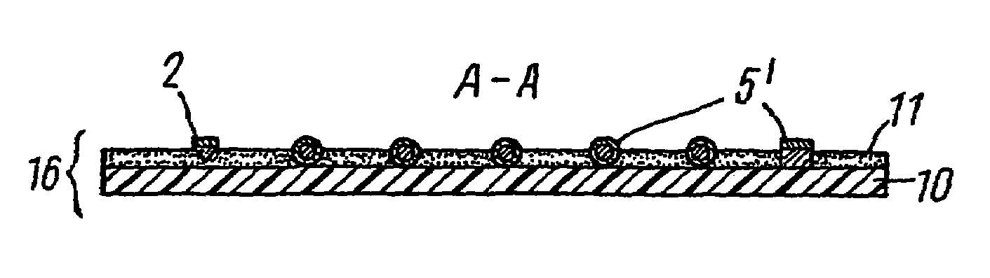
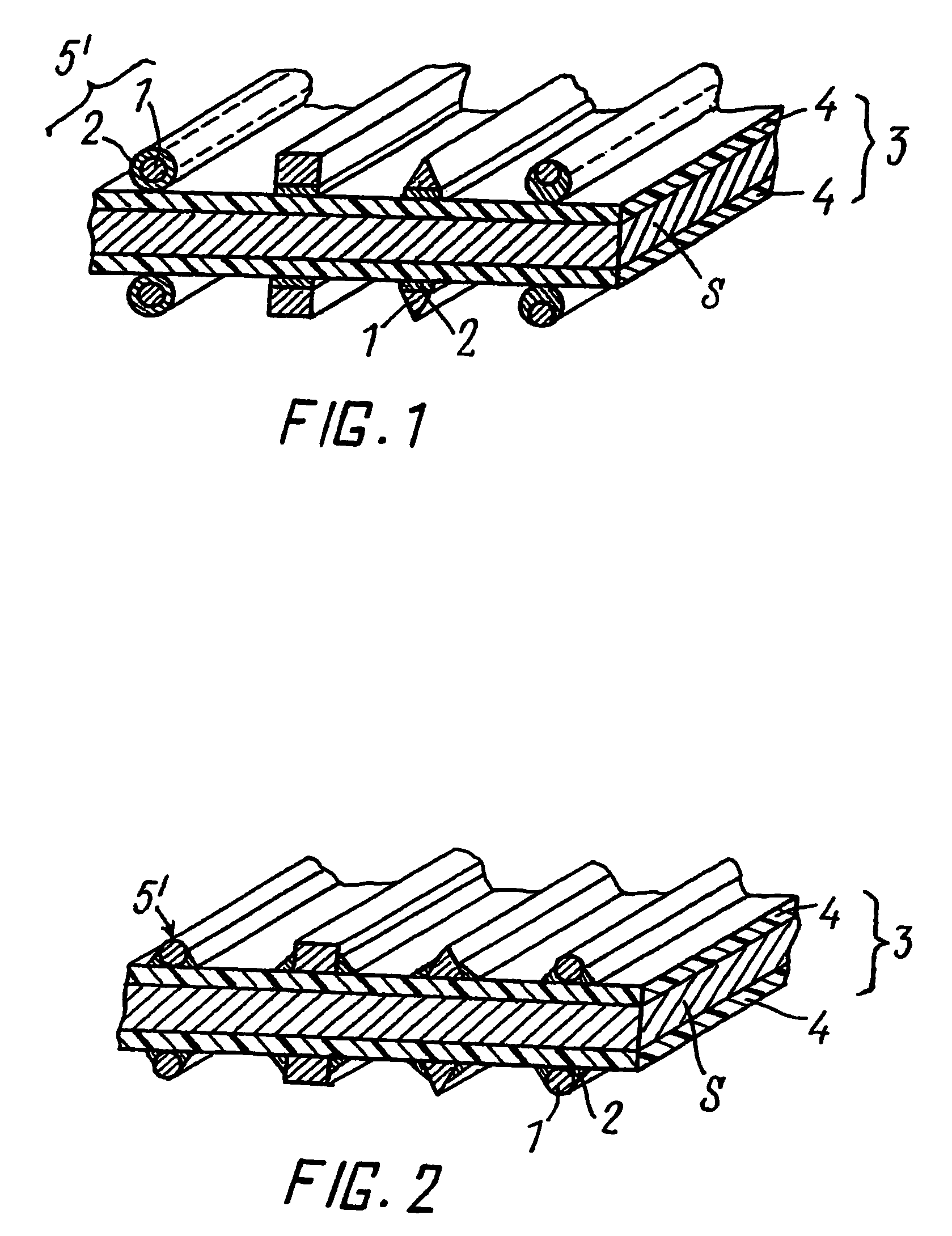
[0065]FIG. 1 shows a semiconductor structure S, for example Silicon (n+n (or p) p+), the upper surface of which (always in relation to the depiction in the figure) is covered with an anti-reflective, transparent, electrically conductive coating 4 such as, for example, Indium-Tin-Oxide (ITO). The element S can also consist of a thin-film PV element. The lower surface of the element S is coated either with a metal coating (e.g. aluminium) or alternatively with an anti-reflective, transparent, electrically conductive coating 4. The element S and the upper coating 4 form together with the metal coating (not depicted) or the second, lower ITO-coating 4 a unit, hereinafter referred to as a wafer 3. The two surfaces of the wafer 3 are in contact with the metallic wires 1, which are coated with a coating 2 consisting of an alloy having a low melting point. The wires 1 may be completely coated with the alloy coating 2 or only partly coated on the side or sides facing the surface to be contac...


PUM


Abstract

An electrode for contacting an electrically conductive surface of a photovoltaic element includes an electrically insulating optically transparent film, an adhesive layer provided on a planar surface of the film, and a plurality of substantially parallel, electrically conductive wires embedded into the adhesive layer. The plurality of wires lies over the planar surface of the film. A part of the surfaces of the wires protrude from the adhesive layer. At least the part of the surfaces protruding from the adhesive layer are covered by a coating consisting of an alloy having a low melting point to solder the wires to the electrically conductive surface and to a first terminal bar. The adhesive layer has a thickness less that a thickness of the wires embedded therein.

Description

CROSS-REFERENCES TO RELATED APPLICATIONS[0001]This document is submitted, pursuant to 35 U.S.C. § 371, as the National Stage of International Application (WO 2004 / 021455A1) filed 21 Aug. 2003, which in turn has already properly claimed priority to German Application (102 39 845.3) filed 29 Aug. 2002.BACKGROUND OF THE INVENTION[0002]The invention relates to an electrode for contacting electrically conductive surfaces, in particular for contacting one or a plurality of photovoltaic (PV) elements being part of a photovoltaic cell or solar cell. The invention further relates to photovoltaic cells produced with this electrode.[0003]The generation of electrical energy using photovoltaic technology has reached a high standard. However, the production of PV cells and PV modules is still rather complicated and expensive. Also the efficiency of energy generation using PV modules with a maximum efficiency of about 17 percent is rather low. From an economic point of view the generation of elect...

Claims


Application Information

Patent Timeline
Patent Type & Authority Patents(United States)
IPC IPC(8): H01L31/00H01L31/04H01L31/0224H05K3/10
CPCH01L31/022425H01L31/0508H01L31/0512H05K3/10Y02E10/50H01L2924/0002H01L2924/00H01L31/0224
Inventor RUBIN, LEONID B.RUBIN, GEORGE L.
Owner MEYER BURGER AG
Why Eureka
Try Eureka