Fiber optics laser perforation tool

a fiber optics and laser technology, applied in manufacturing tools, welding/soldering/cutting articles, borehole/well accessories, etc., can solve the problems of serious safety and security concerns, substantial reduction in production rate, and production rate reduction

Inactive Publication Date: 2004-12-23
GAS TECH INST
View PDF11 Cites 121 Cited by
  • Summary
  • Abstract
  • Description
  • Claims
  • Application Information

AI Technical Summary

Benefits of technology

[0006] It is a further object of this invention to provide a method and apparatus for perforating the well casing of a wellbore which eliminates safety and security risks.
[0007] It is yet a further object of this invention to provide a method and apparatus for perforating the well casing of a wellbore which eliminates the damage to formations which reduces fluid production arising from the use of conventional perforation techniques.
[0008] It is another object of this invention to provide a method and apparatus for perforating the well casing of a wellbore which results in the formation of a long and clean flow path between the fluid reservoir and the wellbore.
[0009] These and other objects of this invention are addressed by a high power laser disposed above ground coupled with a fiber optic cable that transmits laser energy downhole. On the end of the fiber optic cable is a mechanical means that allows for precise control over the motion and location of the fiber optic cable. Such mechanical means are capable of maintaining the cable steady in the center of the hole, or at any other specific location. After the laser penetrates the wellbore casing and cement, the fiber optic cable can be transported through each medium into the actual hole, allowing for the creation of a much deeper perforation. The apparatus is capable not only of drilling deeper into the perforated opening, but also of acting upon the surface of the perforation. Different types of laser treatments can be employed to yield fully vaporized (high permeability), porous melt (moderate permieability) or sealed (impermeable) rock layers. These different treatments are required to cope with the different strengths and stabilities of the rock formations encountered. The desired results can be obtained by manipulating simple laser parameters, such as laser power and exposure time.

Problems solved by technology

However, there are numerous problems with this approach.
First, the melt from shaped charges or debris from the bullet impact usually reduces the permeability of the producing formations resulting in a substantial reduction in production rate.
Second, these techniques involve the transportation and handling of high power explosives and are causes of serious safety and security concerns.
Third, the impact of the bullet into the formation also produces fine grains that can plug the pore throat, thereby reducing the production rate.

Method used


Image

  • Fiber optics laser perforation tool
  • Fiber optics laser perforation tool
  • Fiber optics laser perforation tool

Examples


Embodiment Construction

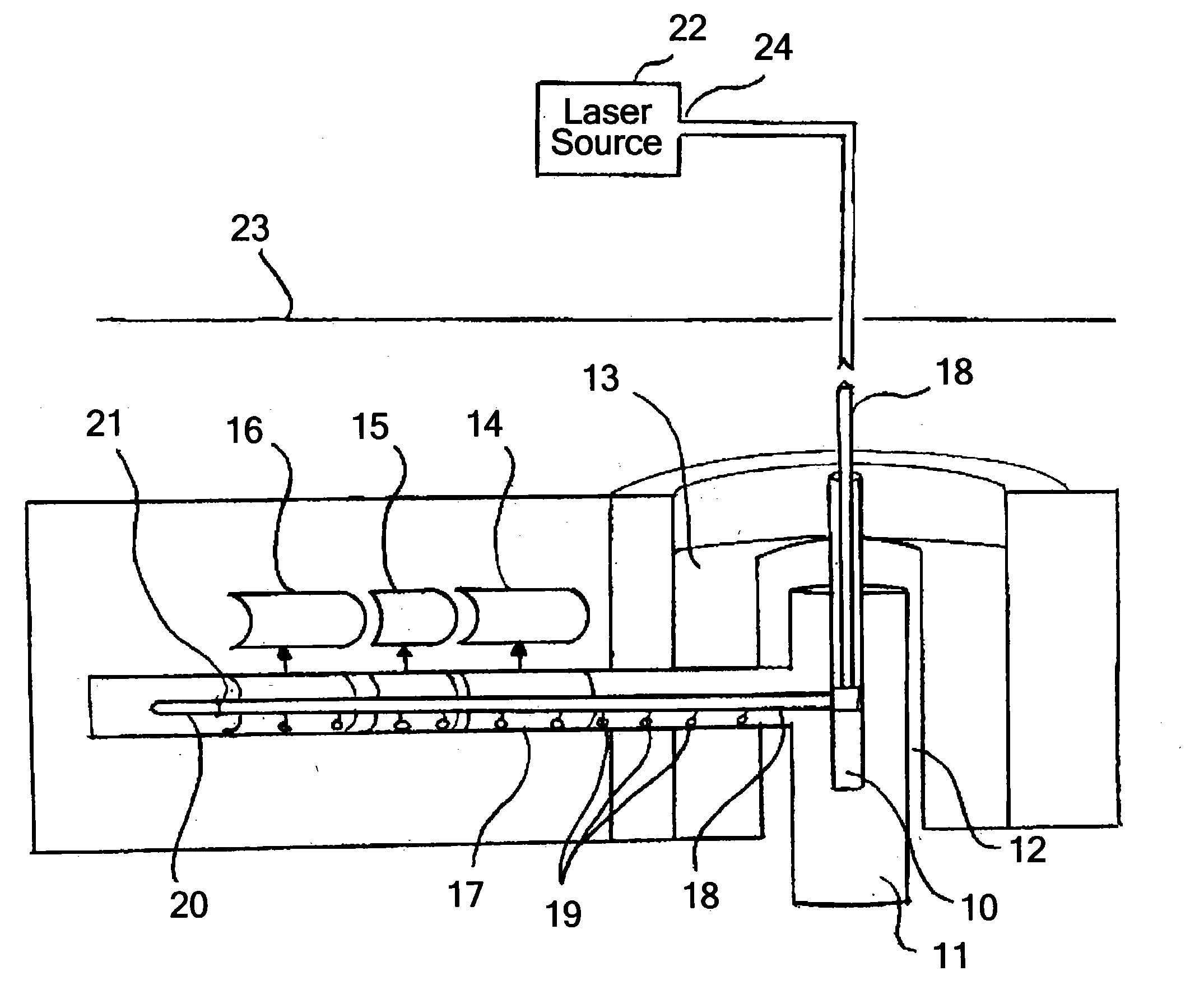
[0018] FIG. 1 shows a fiber optic laser perforation tool in accordance with one embodiment of this invention disposed within a wellbore 10 and extending through casing 11, cement 12 and rock formation 13 into tunnel 17. As shown, the fiber optic laser perforation tool comprises a fiber optic cable 18 having a laser input end 24 and a laser output end 21. Attached to laser input end 24 is a laser source 22, which is disposed above the ground 23. By virtue of this arrangement, there are no physical limitations, such as weight and size, on the downhole portion of the tool. The fiber optic laser perforation tool comprises two inputs (not shown), one of which provides power for the motion system and the other of which provides power for the laser.

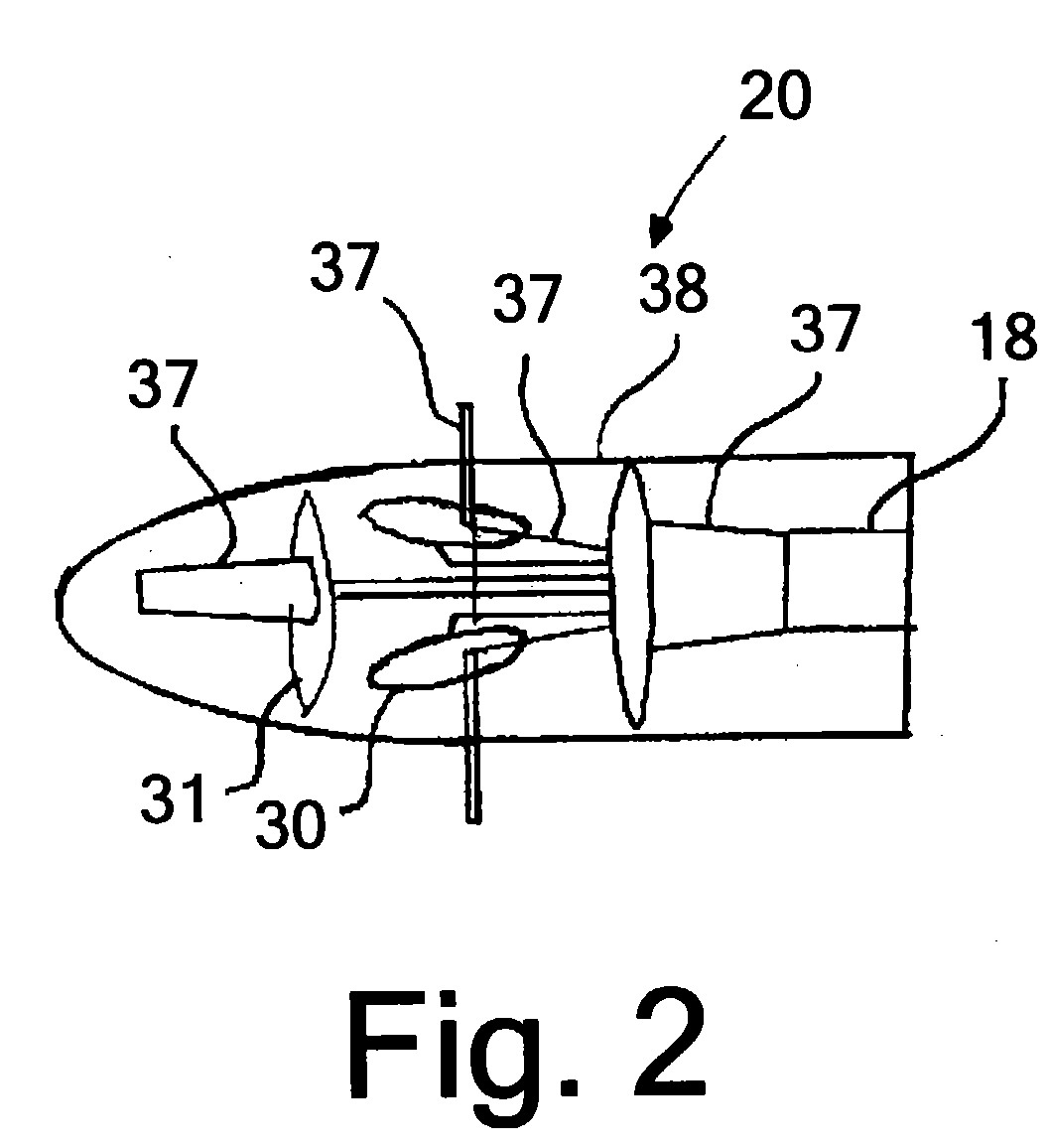
[0019] Connected to laser output end 2:1 of fiber optic cable 18 is laser head 20, the details of which are shown in FIGS. 2 and 3. Laser head 20 comprises a housing 38, which, in accordance with one preferred embodiment of this invention, is a ...


PUM

PropertyMeasurementUnit
transparentaaaaaaaaaa
flexibleaaaaaaaaaa
permeabilityaaaaaaaaaa

Abstract

An apparatus for perforation of wellbore walls, which apparatus includes a fiber optic cable having a laser input end and a laser output end. A laser source is operably connected to the laser input end and a laser head is connected to the laser output end. The laser head includes a laser control components for controlling at least one laser beam characteristic. Laser head control elements for controlling the motion and location of the laser head are operably connected to the fiber optic cable. The laser head is enclosed in a protective housing, which protects the fiber optic cable and elements, such as reflectors and lenses for controlling the laser beam emitted by the fiber optic cable disposed therein, from the harsh environments encountered in downhole operations.

Description

[0001] 1. Field of the Invention[0002] This invention relates to a method and apparatus for completion of oil, gas and / or hydrothermal wells. More particularly, this invention relates to the application of laser energy for initiating or promoting the flow of a desired resource, e.g. oil, into a wellbore, referred to herein as well completion.[0003] 2. Description of Related Art[0004] Once the drilling of a well has been completed, fluid flow into the well is initiated by perforation of the well casing or liner. Such perforations are created using bullets or shaped charges for establishing flow of oil or gas from the geologic formations into the wellbore. The perforations typically extend a few inches into the formation. However, there are numerous problems with this approach. First, the melt from shaped charges or debris from the bullet impact usually reduces the permeability of the producing formations resulting in a substantial reduction in production rate. Second, these technique...

Claims


Application Information

Patent Timeline
Patent Type & Authority Applications(United States)
IPC IPC(8): B23K26/12B23K26/38E21B43/11
CPCB23K26/0639B23K26/0648B23K26/0665B23K26/12B23K26/381E21B43/11B23K26/128B23K26/4075B23K26/064B23K26/382B23K26/40B23K2103/50
Inventor BATARSEH, SAMIH
Owner GAS TECH INST
Why Eureka
Try Eureka