
Trash receptacle unit

Inactive Publication Date: 2006-09-19
ROUSE JASON C +1
View PDF17 Cites 8 Cited by
  • Summary
  • Abstract
  • Description
  • Claims
  • Application Information

AI Technical Summary

Benefits of technology

[0011]It is a main object of the present invention to provide a trash receptacle that can be easily manipulated.
[0012]It is another object of the present invention to provide a trash receptacle that can be used in connection with a trash bag which can be easily placed and removed.
[0013]It is another object of the present invention to provide a trash receptacle that can be easily and efficiently cleaned.
[0014]It is another object of the present invention to provide a trash receptacle that is stable yet easy to manipulate.SUMMARY OF THE INVENTION
[0016]Using the trash receptacle unit embodying the present invention will permit the container to be easily manipulated for loading, unloading and cleaning. The heavy base provides stability, but since the tubular member is removed from the heavy base, the heavy base will not interfere with movement of the trash bag. A trash bag can be easily placed and removed for disposal.

Problems solved by technology

However, one problem that the inventor has identified is the difficulty in placing a new trash bag into a container and then removing a full bag from the container.
Often, air pressure and suction make removing a filled trash bag from a container difficult.
This is especially a problem if the bag is heavy or bulky and / or the person is disabled.
In some situations, a filled trash bag is quite heavy, and, in fact, may be heavier than the container itself.
Therefore, removing a filled trash bag from a container may be difficult and cumbersome.
Still further, placing an empty bag into a trash container may be difficult and onerous.
While the inventor is aware of some trash containers that have units for storing and dispensing trash bags, these containers really do not solve the problem as a user must still reach into a trash container to deploy a fresh bag and then still must wrestle with a filled bag to remove that filled bag from the container.
Often, a trash container becomes soiled and must be cleaned.
This can be difficult if the person is disabled in any way.
At any rate, this is an inefficient way to clean such containers.
One problem with many of the trash containers known to the inventor is the stability thereof.
In windy conditions, some of these containers tend to tip over and spill.
However, such bases make the containers difficult to handle and manipulate, especially when removing a trash bag or cleaning the container.

Method used


Image

  • Trash receptacle unit
  • Trash receptacle unit

Examples


Embodiment Construction

[0020]Other objects, features and advantages of the invention will become apparent from a consideration of the following detailed description and the accompanying drawings.

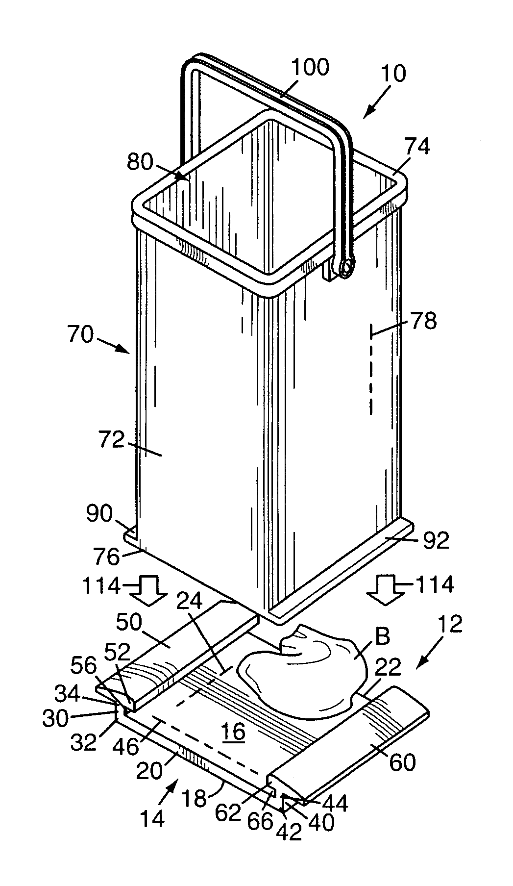
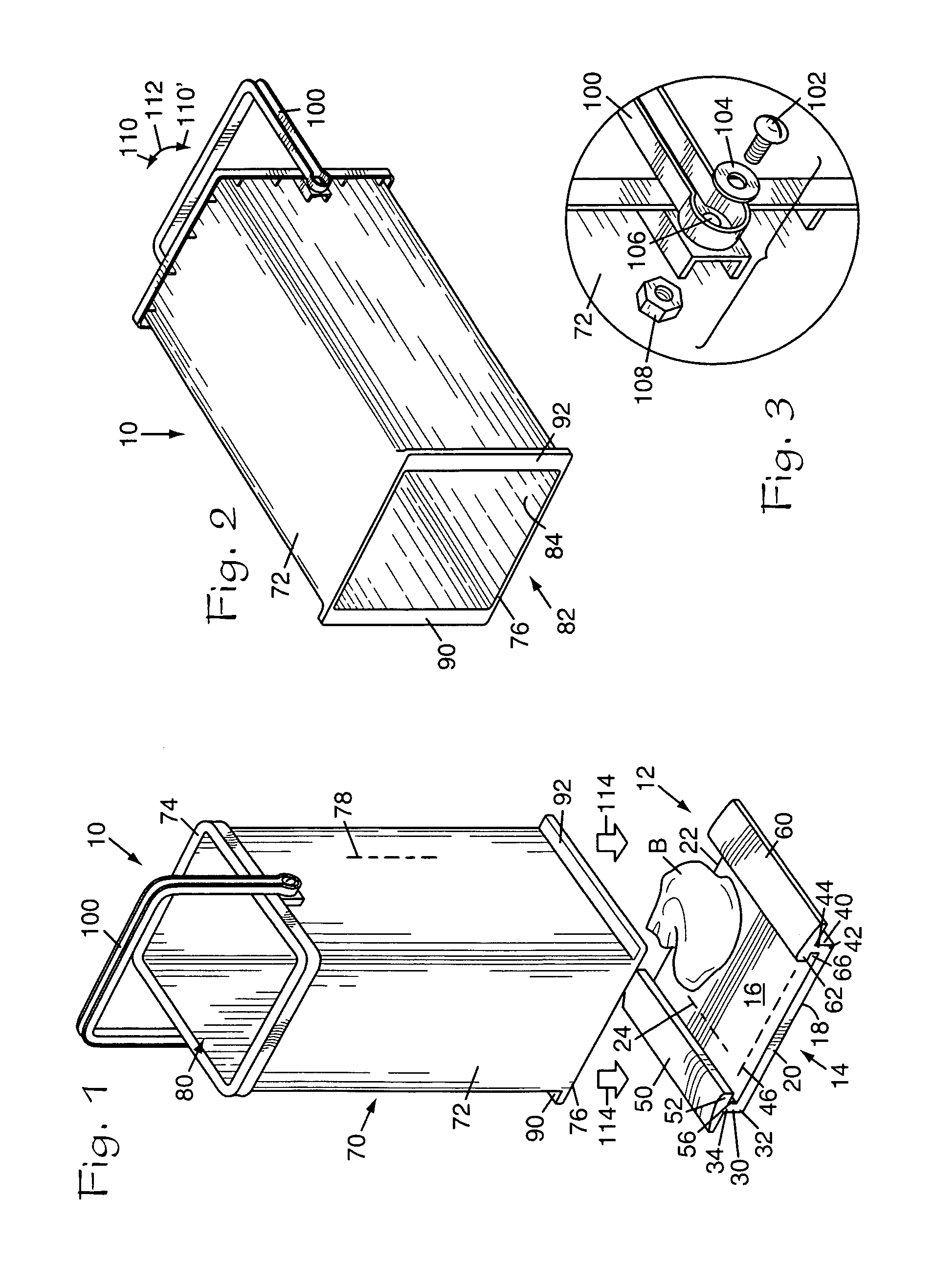
[0021]Referring to the Figures, it can be understood that the present invention is embodied in a trash receptacle unit 10 that achieves the above-stated objectives.

[0022]Unit 10 comprises a base member 12 which includes a U-shaped body 14. Body 14 includes a first surface 16, which is a top surface when base member 12 is in use, and a second surface 28, which is a bottom surface when base member 12 is in use. Base member 12 further includes a first side wall 20, a second side wall 22, and a transverse axis 24 which extends between first side wall 20 and second side wall 22.

[0023]A first end wall 30 has a proximal end 32, which is unitary with first surface 16, and a distal end 34, which is spaced apart from first surface 16. A second end wall 40 has a proximal end 42, which is unitary with first surface 16, and a ...


PUM


Abstract

A tubular member is releasably mounted on a base and encircles a trash bag that rests on the base. Once the trash bag is filled, the tubular member is released from the base and removed from the filled trash bag. The filled trash bag can then be removed and discarded.

Description

BACKGROUND OF THE INVENTION[0001]The present invention relates to the general art of receptacles, and to the particular field of horizontally attached receptacles which can be detached.[0002]Many people use trash bags to store trash. Generally, these trash bags must be placed into a trash container, filled and then removed for disposal. To this end, the inventor is aware of several different types of trash bags and trash receptacles that use trash bags.[0003]However, one problem that the inventor has identified is the difficulty in placing a new trash bag into a container and then removing a full bag from the container. Often, air pressure and suction make removing a filled trash bag from a container difficult. This is especially a problem if the bag is heavy or bulky and / or the person is disabled.[0004]Therefore, there is a need for a trash receptacle that can be easily manipulated.[0005]In some situations, a filled trash bag is quite heavy, and, in fact, may be heavier than the co...

Claims


Application Information

Patent Timeline
IPC IPC(8): B65D8/00B65D8/04
CPCB65F1/06B65F1/068Y10S220/908B65F2230/15
Inventor ROUSE, JASON C.ROUSE, LINDSEY JO
Owner ROUSE JASON C
Learn More