

Specimen centrifuge apparatus
a centrifuge and specimen technology, applied in the direction of centrifuges, instruments, specific gravity measurement, etc., can solve the problems of consuming energy in vain, requiring a relatively large space for the apparatus to centrifuge a number of specimens at once, and requiring a relatively large spa
- Summary
- Abstract
- Description
- Claims
- Application Information
AI Technical Summary
Benefits of technology
Problems solved by technology
Method used
Image

Examples
first embodiment
(First Embodiment)
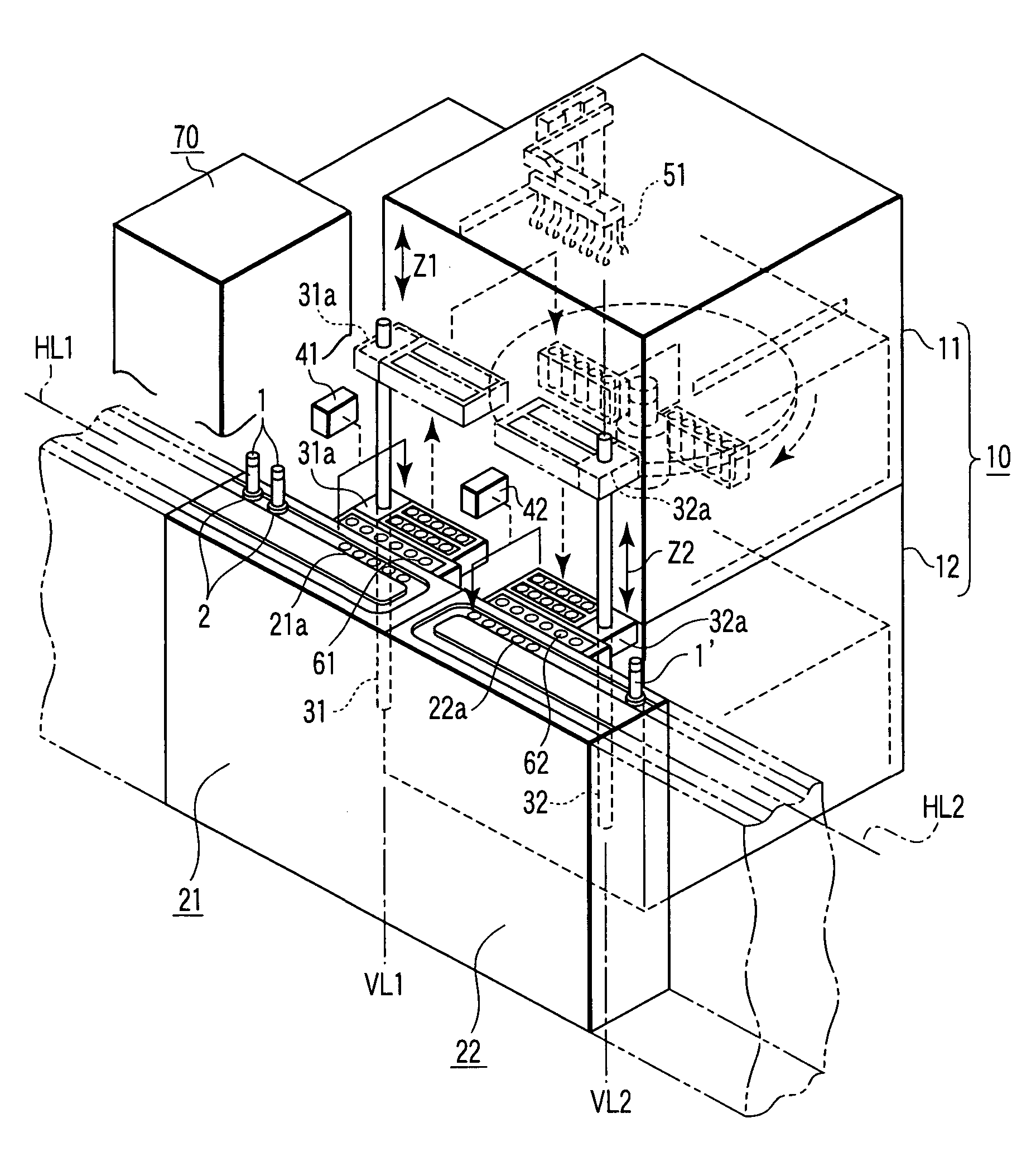
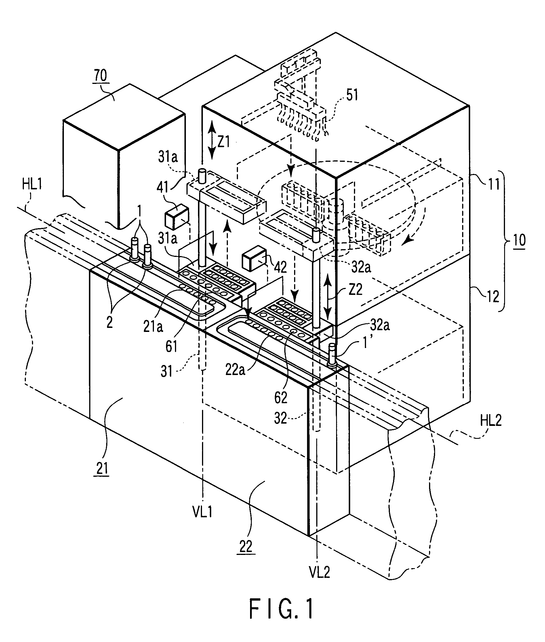
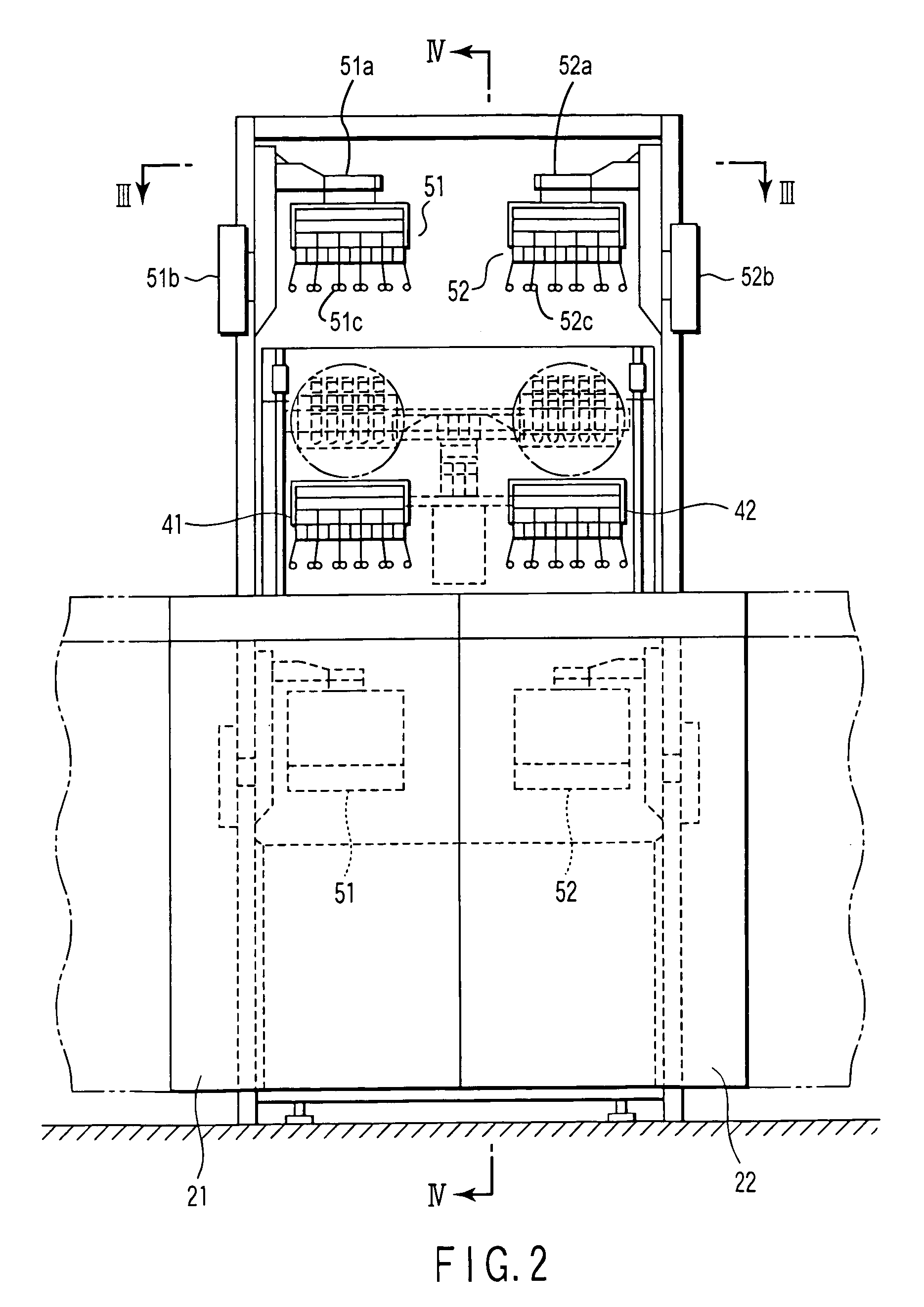
[0021]As shown in FIGS. 1 to 4, a specimen centrifuge apparatus according to a first embodiment of the invention comprises a centrifuge device 10 including a plurality of specimen centrifuge units 11 and 12 (two in the first embodiment). The specimen centrifuge units 11 and 12 are stacked one on another.
[0022]The specimen centrifuge units 11 and 12 are stored in their respective first and second cabinets 110 and 120, as shown in FIG. 4. The cabinets 110 and 120 are formed by vertically partitioning a rectangular parallelepiped housing 100 into two.
[0023]Each of the, specimen centrifuge units 11 and 12 has a motor M, a rotor R and a position sensor C. The motor M is set up on the floor of the corresponding one of the cabinets 110 and 120. The rotor R is rotated by the motor M. The position sensor C senses a position of the rotation of the rotor R and positions the rotor R to easily load and unload specimen containers, which will be described later.
[0024]The rotor R ...
second embodiment
(Second Embodiment)
[0061]FIG. 7 is a top view of the principal part of a specimen centrifuge apparatus according to a second embodiment of the invention.
[0062]The second embodiment differs from the first embodiment as follows. The carry-in conveyor 21 and carry-out conveyor 22 are arranged in parallel to each other and the centrifuge device 10 is interposed between the conveyors 21 and 22. The locations of container inserting position IN and container removing position OUT on the rotor R are 180 degrees different from each other.
[0063]The second embodiment has the advantage that the conveyance lanes of the carry-in conveyor 21 and carry-out conveyor 22 each have only to be formed straightly. Since the second embodiment is the same as the first embodiment except for the above, its detailed descriptions are omitted.
third embodiment
(Third Embodiment)
[0064]FIG. 8 is a top view of the principal part of a specimen centrifuge apparatus according to a third embodiment of the invention.
[0065]The third embodiment differs from the first embodiment as follows. A plurality of (four in the third embodiment) notches K are formed in the circumference of rotating disc DX of rotor RX of centrifuge device 10. Four specimen container buckets BX each shaped like a rectangular parallelepiped are arranged in their respective notches K such that the longitudinal direction of each bucket BX is set toward the tangent to the rotating disc DX.
[0066]The third embodiment also differs from the first embodiment as follows. The locations of carry-in and carry-out conveyors 21 and 22 are 90 degrees different from each other, and the specimen containers are inserted at and removed from the container inserting and removing positions IN and OUT which are spaced by 90 degrees on the rotor RX.
[0067]The invention can be applied to a centrifuge de...
PUM
| Property | Measurement | Unit |
|---|---|---|
| time | aaaaa | aaaaa |
| rotation directions | aaaaa | aaaaa |
| energy | aaaaa | aaaaa |
Abstract
Description
Claims
Application Information