Roll-up floor tile system and method

a floor tile and roll-up technology, applied in the field of floor tiles, can solve the problems of time-consuming and inefficient, and achieve the effect of reducing the number of tiles

Inactive Publication Date: 2006-10-03
SNAP LOCK INDS
View PDF47 Cites 156 Cited by
  • Summary
  • Abstract
  • Description
  • Claims
  • Application Information

AI Technical Summary

Benefits of technology

[0008]Each of the tile in accordance with the invention includes at least one orthogonally extending hinge or fold line, such that a multi-tile floor can be rolled up, beginning at one floor-edge, without the need to disassemble the floor into its individual tile.

Problems solved by technology

This is, of course, time consuming and very inefficient, particularly where the floor tiles are to be reinstalled in a short period of time.

Method used


Image

  • Roll-up floor tile system and method
  • Roll-up floor tile system and method
  • Roll-up floor tile system and method

Examples


Embodiment Construction

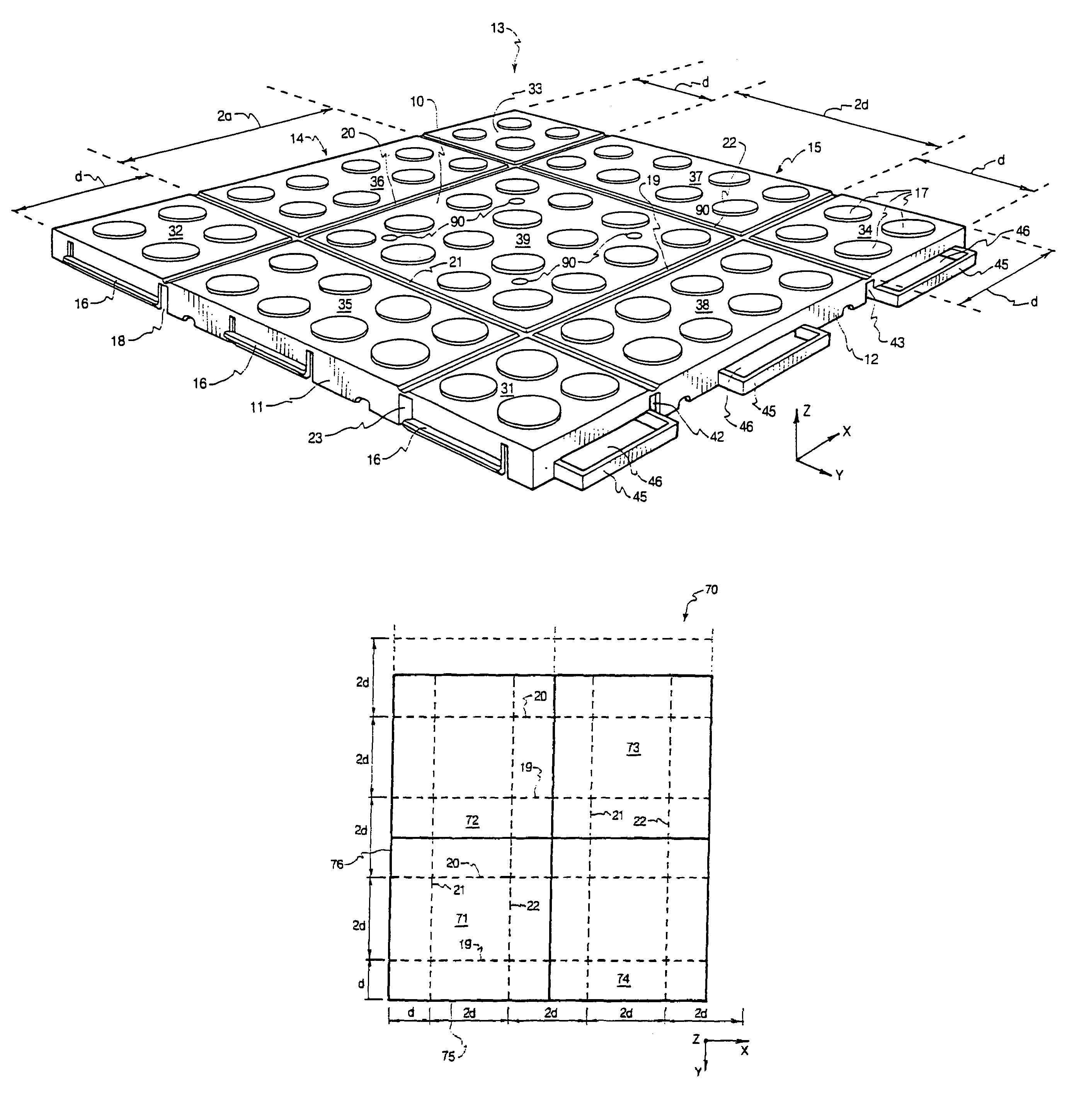
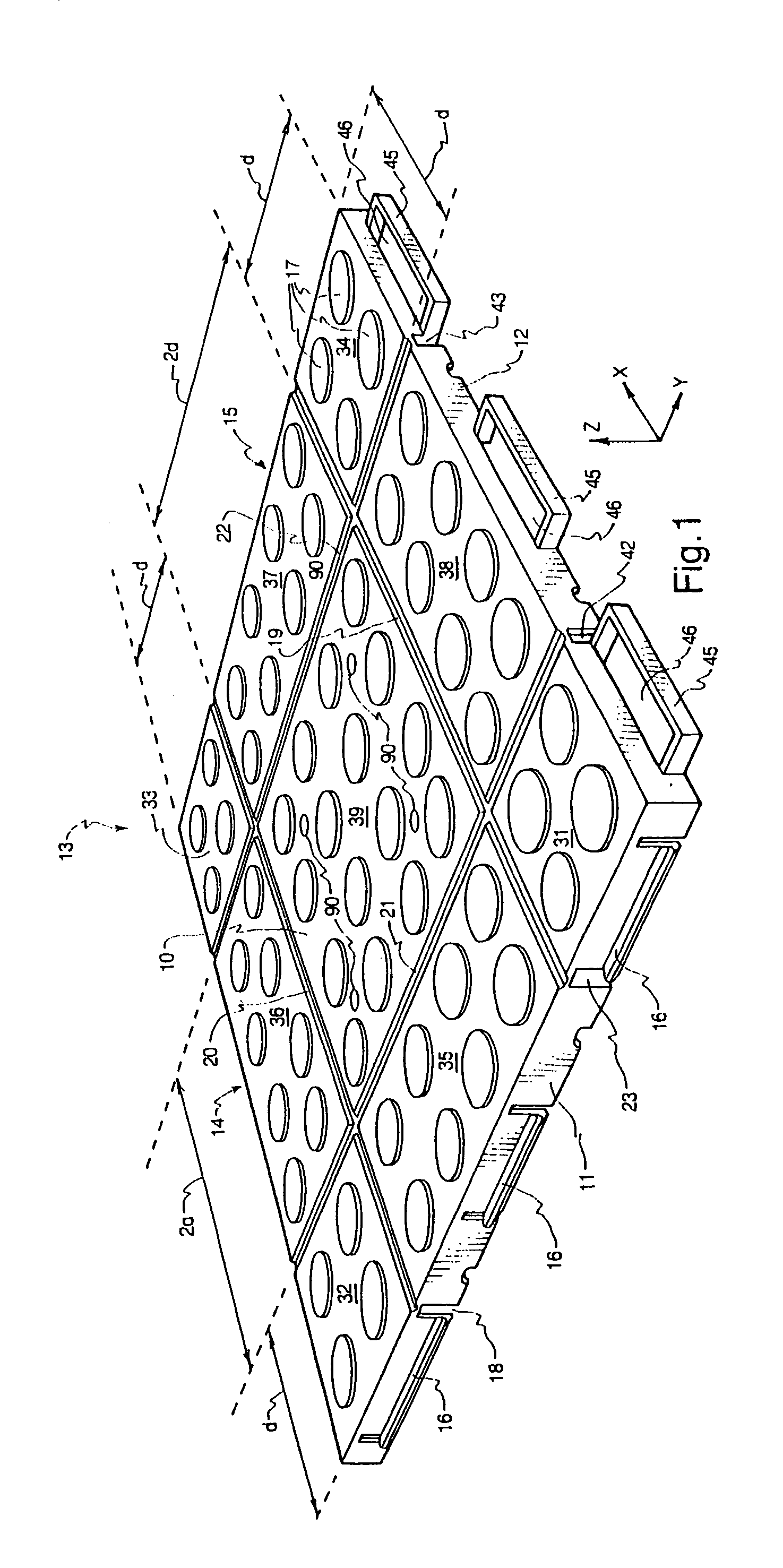
[0028]FIG. 1 shows the top or traffic-carrying surface 10 of a tile 13 constructed and arranged in accordance with the invention. An X-Y-Z three-dimensional coordinate system is shown relative to the tile apparatus shown in FIG. 1.

[0029]The top surface 10 of tile 13 (also seen in FIG. 3) is a generally flat, planar surface that extends in the X-Y plane of the tile. In one embodiment, top surface 10 is a one-foot by one-foot square.

[0030]Top surface 10 of tile 13 includes a relatively high-friction surface, such as, for example, a slightly raised pattern of circles 17 that provide a degree of friction to top surface 10. Of course, any other surface patterns or textures can be used to provide a traction-type of top surface 10 without departing from the scope of the present invention.

[0031]When tile 13 is to be used out of doors, drain holes 90 may be provided within top surface 10. For purposes of drawing simplicity, only a few drain holes 90 are shown in FIGS. 1, 3.

[0032]In accordanc...


PUM

PropertyMeasurementUnit
angleaaaaaaaaaa
widthaaaaaaaaaa
widthaaaaaaaaaa

Abstract

A plurality of interlocking tile pieces form a generally flat traffic-carrying surface. The tile are locked together in a manner to form a plurality of non-bendable tile joints. The tile includes a hinge or fold line along a first axis and a hinge or fold line along a second axis. The hinges allow the multi-tile traffic carrying surface to be rolled up into a hollow tube from any direction along one of the axes, beginning at any edge of the traffic carrying surface. The rolled-up floor covering is made up of a plurality of tile panels.

Description

[0001]This application is a continuation of application Ser. No. 10 / 159,486 filed May 31, 2002 which has issued as U.S. Pat. No. 6,802,159.FIELD OF THE INVENTION[0002]This invention relates to floor tiles, and more particularly to interlocking floor tiles for covering a floor or other surface.BACKGROUND OF THE INVENTION[0003]Floor coverings and ground coverings, both permanent and temporary tiles, are well known. For example U.S. Pat. Nos. 3,438,312, 4,436,779, 4,054,987, 5,791,114, 6,026,625 and 6,098,354 are of interest and are incorporated herein by this reference.[0004]Interlocking floor tiles, of the type that are typically installed on top of an existing floor, have traditionally required installation by placing one tile down on the floor after the other and interlocking the respective tiles through some type of interlocking system. When the tiles need to be removed, even temporarily, the tiles have traditionally been required to be disassembled one tile at a time. This is, of...

Claims


Application Information

Patent Timeline
Patent Type & Authority Patents(United States)
IPC IPC(8): E04F15/16E01C5/20E04F15/10
CPCE01C5/20E04F15/10E01C2201/12E04F2201/0594E04F15/02194E04F15/105
Inventor KOTLER, DANIEL
Owner SNAP LOCK INDS
Why Eureka
Try Eureka