Mounting system for mounting an alignment instrument on a vehicular wheel that uses any known lug bolt pattern

a technology of lug bolt pattern and mounting system, which is applied in the direction of instruments, using fluid means, measurement devices, etc., can solve the problems of inability to achieve accurate alignment of alignment instruments in conjunction with tire rims, damage to tire rims often occurring, and tire rim damag

Active Publication Date: 2006-10-10
PELLEGRINO DEAN S
View PDF34 Cites 12 Cited by
  • Summary
  • Abstract
  • Description
  • Claims
  • Application Information

AI Technical Summary

Problems solved by technology

Tire rims sometimes may be damaged and may be slightly out of round or slightly inclined relative to the wheel hub.
Such damage frequently occurs by the tire and the rim coming into hard contact with an uneven roadway, such as a chuckhole or a curb.
Using of the alignment instrument in conjunction with the tire rim does not achieve an accurate alignment because the rim itself is not correctly aligned relative to the wheel hub on which it is mounted.
Mounting of an alignment instrument on such a vehicular rim frequently causes scratching or denting of the rim.
Replacement of each rim can run several hundred dollars in cost to the mechanic or tire shop.
Currently, some tire rims no longer are being manufactured with this annular raised lip.
Therefore, there is no known way to mount the alignment instrument onto the tire rim.
The result is the alignment is of poor quality and properly handling of the vehicle is not obtained.
Uneven tire wear is also obtained.

Method used


Image

  • Mounting system for mounting an alignment instrument on a vehicular wheel that uses any known lug bolt pattern
  • Mounting system for mounting an alignment instrument on a vehicular wheel that uses any known lug bolt pattern
  • Mounting system for mounting an alignment instrument on a vehicular wheel that uses any known lug bolt pattern

Examples


Embodiment Construction

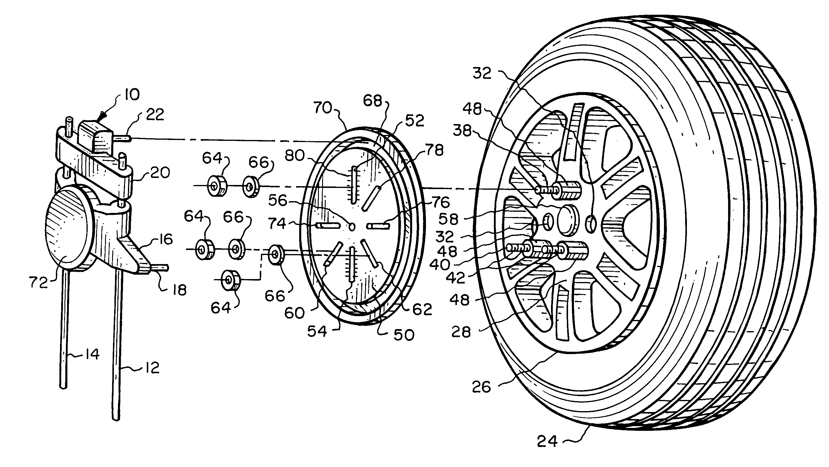
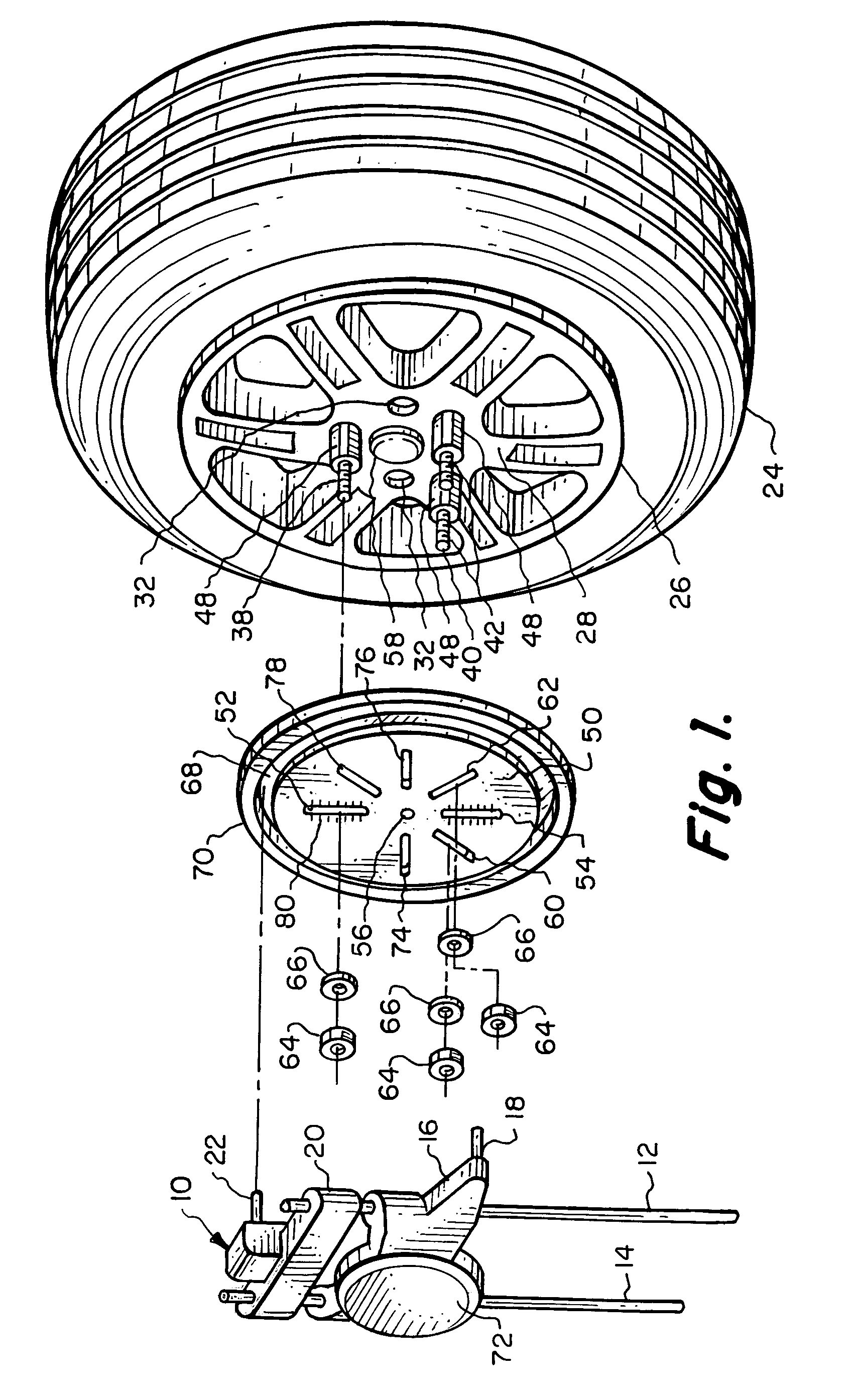
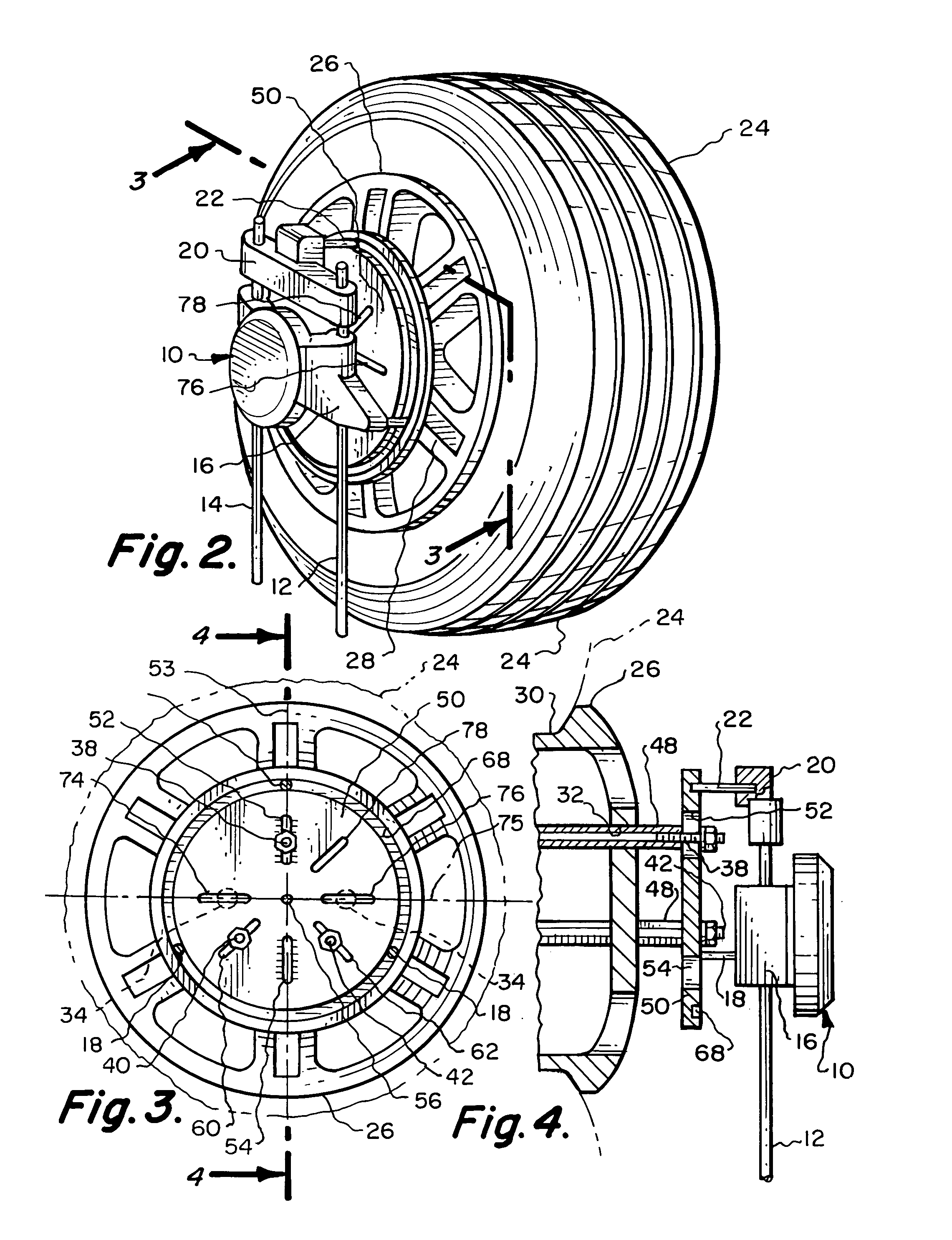
[0022]Referring particularly to the drawings, there is shown in FIGS. 1 and 2 a conventional alignment instrument which is generally referred to as an aligning sensing head 10. The specific construction of the sensing head 10 does not constitute any specific part of this invention but is deemed to be prior art. The sensing head 10 includes a housing 16. Housing 16 is slidably mounted on a pair of parallel spaced apart rods 12 and 14. The housing 16 has two in number of fingers 18 mounted thereon. Each of the fingers 18 comprise small protruding rods that are located parallel to each other. The housing 16 is slidably mounted on the rods 12 and 14. The rods 12 and 14 are fixedly secured to a crossbar 20. Mounted on the crossbar 20 and located equidistantly spaced from each of the rods 12 and 14 is another finger 22. The purpose of the fingers 18 and 22 will be explained further on in the specification.

[0023]Referring particularly to FIGS. 1 and 2, there is shown a vehicular tire 24 wh...


PUM


Abstract

A mounting system for mounting an alignment instrument onto a vehicular wheel which is to be used to align the wheel of the vehicle. The mounting system includes a mounting plate which has an engagement structure located directly adjacent the peripheral edge of the mounting plate. At least a pair of the lug nuts, and preferably three in number of the lug nuts, of the vehicular wheel are to be removed and replaced with elongated internally threaded sleeves, all the same length, which are substantially longer in length than the lug nuts so that the mounting plate will be mounted in a spaced relationship from the vehicular wheel. The mounting plate includes at least five in number of elongated holes generally radially disposed in a spaced apart arrangement relative to the center of the mounting plate. A fastener assembly is used to fixedly mount the mounting plate onto the elongated internally threaded sleeves. The alignment instrument is then to be clamped onto the mounting plate by engaging with the engagement structure.

Description

BACKGROUND OF THE INVENTION[0001]1. Field of the Invention[0002]The field of this invention relates to a system for mounting of an alignment instrument precisely on a vehicular wheel in order to align that wheel where the alignment instrument does not in and of itself touch the vehicular wheel and the mounting system can be utilized with any known lug bolt pattern on which the vehicle wheel is mounted.[0003]2. Description of the Related Art[0004]The subject matter of the present invention is deemed to be an improvement over U.S. Pat. No. 6,622,389 which is owned by the present inventor. Proper alignment of vehicle wheels is necessary for smooth vibration-free handling of the vehicle and also so the vehicle doesn't have a tendency to drift one way or another on the road. Also, proper alignment of vehicle wheels is a necessary component for even tire wear. To accomplish vehicular alignment, it is necessary to establish the position of certain measurements in conjunction with each vehi...

Claims


Application Information

Patent Timeline
Patent Type & Authority Patents(United States)
IPC IPC(8): G01B5/255G01B21/26
CPCG01B5/255
Inventor PELLEGRINO, DEAN S.
Owner PELLEGRINO DEAN S
Why Eureka
Try Eureka