Structure and method for connecting conducting lines to terminals

a technology of connecting conductors and connectors, applied in the direction of coupling device connections, coupling device details, contact members penetrating/cutting insulation/cable strands, etc., can solve the problems of not being convenient and really laborious

Active Publication Date: 2006-10-10
PENG JOHN
View PDF11 Cites 68 Cited by
  • Summary
  • Abstract
  • Description
  • Claims
  • Application Information

AI Technical Summary

Problems solved by technology

Therefore, it is not so convenient.
In addition, since an operator has to press the cover 11 so as to rotate the cover 11, it is really laborious.

Method used


Image

  • Structure and method for connecting conducting lines to terminals
  • Structure and method for connecting conducting lines to terminals
  • Structure and method for connecting conducting lines to terminals

Examples


Embodiment Construction

[0036]The present invention will now be described more specifically with reference to the following embodiments. It is to be noted that the following descriptions of preferred embodiments of this invention are presented herein for purpose of illustration and description only; it is not intended to be exhaustive or to be limited to the precise form disclosed.

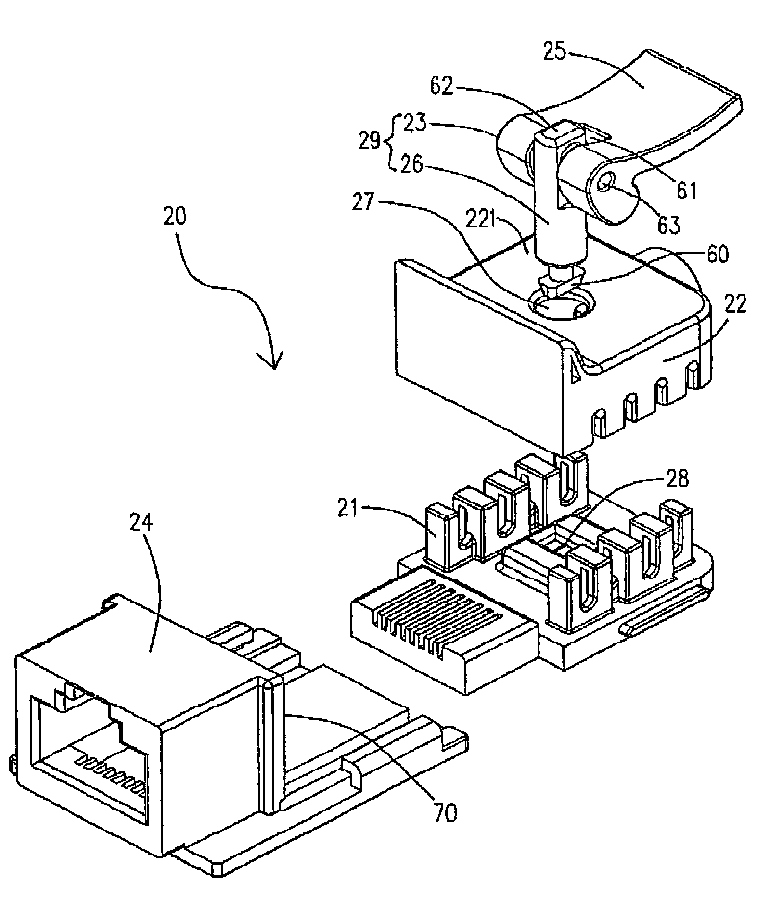
[0037]Please refer to FIG. 2, which shows an exploding view of an insulation displacement connector according to the preferred embodiment of the present invention. As shown in FIG. 2, the insulation displacement connector 20 includes the terminal base 21, the clip 22, and the rotating plate 23, being a pressing handle, the connecting main body 24, the pressing surface 25, the rotating rod 26, the opening 27 formed in an upper wall 221 of the clip 22, and the fastening concavity 28. The concavity 61 of the rotating plate 23 is used for containing the linking end 62 of the rotating rod 26, and the rotating plate 23 is assembled to ...


PUM


Abstract

A connector structure is provided. The connector structure includes a terminal base having plural terminals, a clip device vertically arranged with the terminal base via a positioning piece and including plural conducting lines and a rotating device located on the clip device.

Description

FIELD OF THE INVENTION[0001]The present invention relates to the structure of an insulation displacement connector and the stabbing method used thereby, and more particular to an insulation displacement connector with a rotating plate and the stabbing method used thereby.BACKGROUND OF THE INVENTION[0002]In general, there are plural terminals for being connected to conducting lines in an insulation displacement connector (IDC). The terminals are located in a terminal base, and it is possible that the terminal base is perpendicularly set on a printed circuit board. During the operation, the IDC is usually connected to a network plug via a Keystone Jack.[0003]Please refer to FIG. 1, which shows an insulation displacement connector 10 disclosed in the Taiwan Utility Patent No. 537544. As shown in FIG. 1, the four conducting lines 13, 14, 15 and 16 on the cover 11 would be stabbed by the clips 19 after the cover 11 is rotated around the shaft 18 of the connecting main body 17 to attach t...

Claims


Application Information

Patent Timeline
Patent Type & Authority Patents(United States)
IPC IPC(8): H01R4/24
CPCH01R4/2433
Inventor PENG, JOHN
Owner PENG JOHN
Why Eureka
Try Eureka