Clipping device

a technology of a clipping device and a convex part, which is applied in the direction of fastening means, screws, fastener tools, etc., can solve the problems of difficult to provide the convex part, difficult to reliably prevent an excessive insertion of the pin with a sufficient strength, and the inability to manufacture a low-cost clipping device, etc., to achieve the effect of easy torn o

Inactive Publication Date: 2005-10-06
PIOLAX CO LTD
View PDF42 Cites 32 Cited by
  • Summary
  • Abstract
  • Description
  • Claims
  • Application Information

AI Technical Summary

Benefits of technology

[0030] According to the ninth aspect of the invention, because the inner end sides of the small bridge pieces are connected to the face having the tapered shape at the tip end part of the pin, the small bridge pieces can be made as longer as possible in size, according to an angle of the tapered shape, which renders the small bridge pieces to be more easily torn off ...

Problems solved by technology

Accordingly, the clipping device has been unable to be manufactured at low cost.
However, in case where the pin and the grommet have been integrally molded, even though it has been intended to provide means for preventing the pin from being excessively inserted into the grommet, for example, a convex part for receiving a stepped part of the pin, on the body part of the grommet, it has been technically difficult to provide the convex part, since the pin which has been integrally molded so as to cover an upper part of an opening in the grommet may become an obstacle.
Even though the convex part having a small protruding amount can be provided, it has been difficult for this co...

Method used


Image

  • Clipping device
  • Clipping device
  • Clipping device

Examples


first embodiment

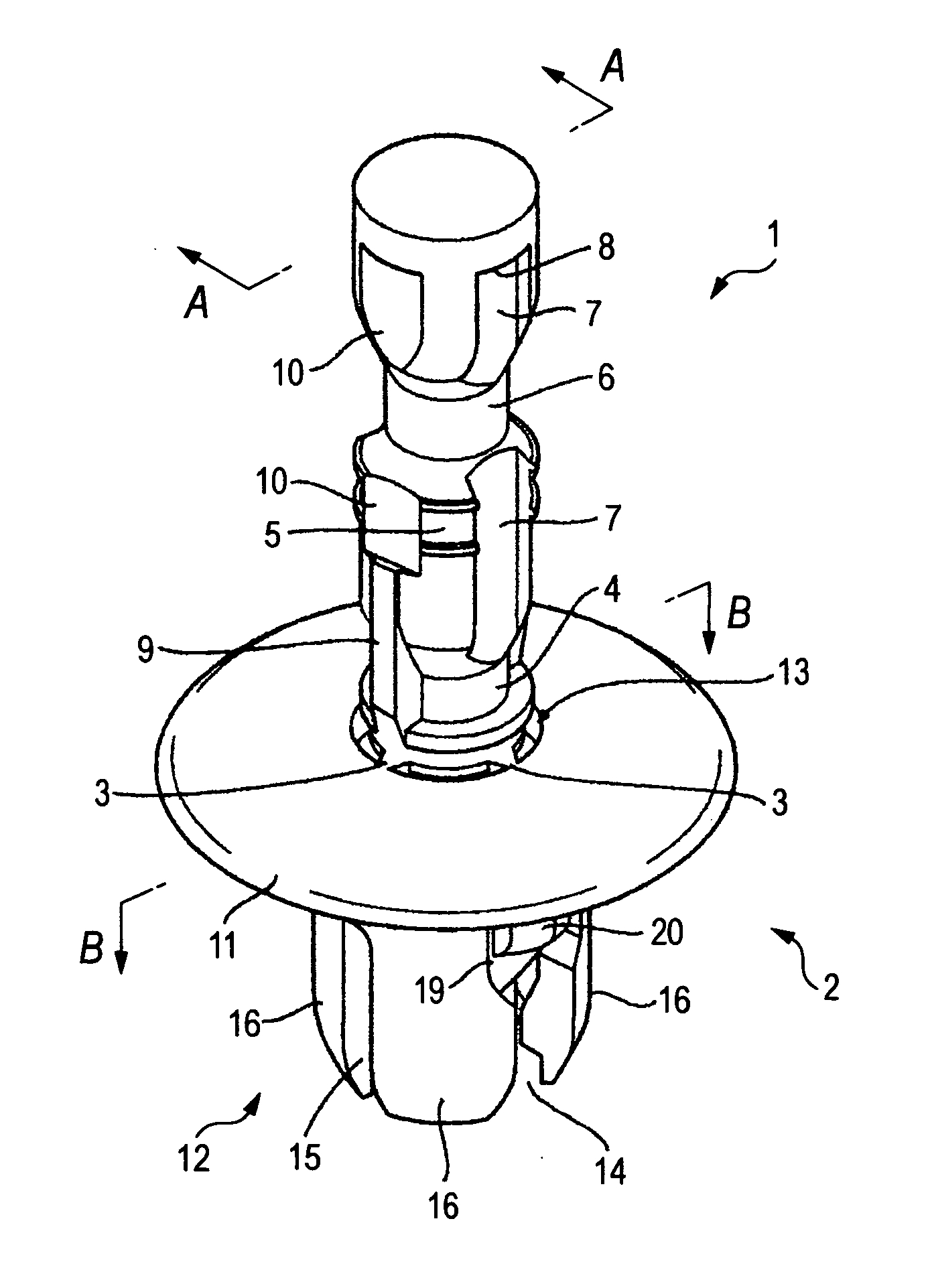
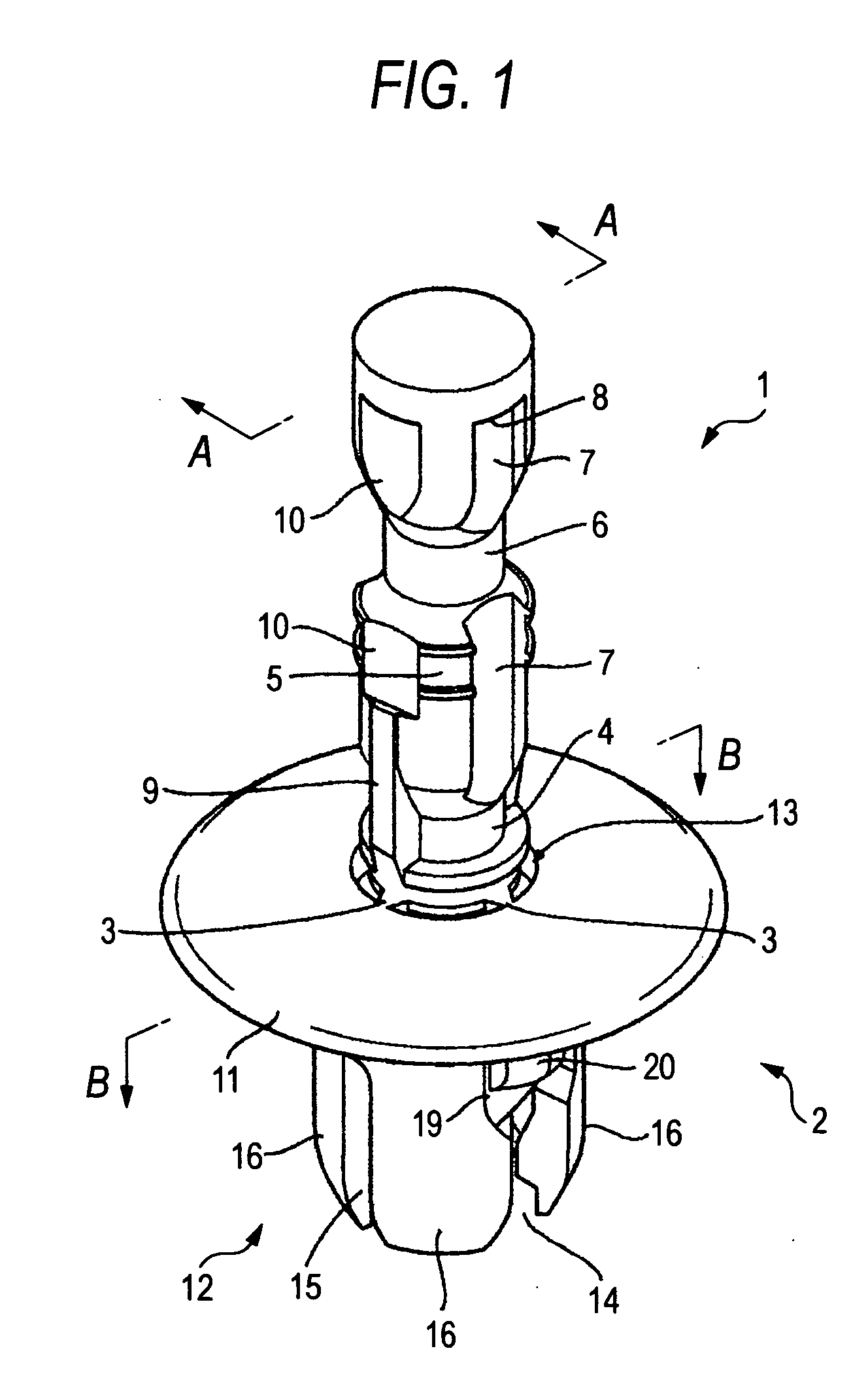
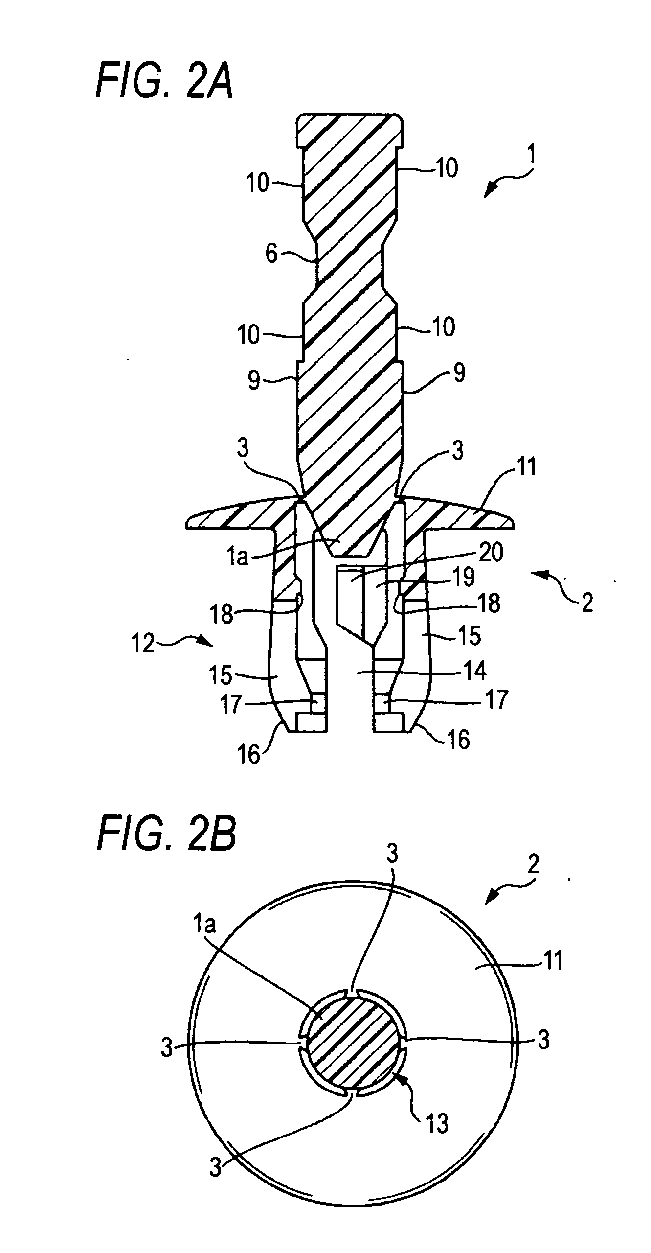
[0043] An object of the invention is to provide an inexpensive clipping device of push-push type in which a pin is provided with a stepped part which can be formed by integral molding, and a grommet is provided with a swinging piece which can be formed by integral molding, when the pin and the grommet are integrally molded of synthetic resin, whereby the pin will be prevented from being excessively pushed into a body part of the grommet.

[0044] Now, the invention will be described in detail, referring to a preferred embodiment as shown in the drawings. Although a clipping device in this embodiment includes two components, namely, a pin 1 and a grommet 2 in the same manner as in the prior art, a characteristic feature of this clipping device is that the pin 1 and the grommet 2 are integrally molded of synthetic resin, as shown in FIG. 1. On occasion of integrally molding, the pin 1 and the grommet 2 are displaced from each other in an axial direction, and coupled by four small bridge...

second embodiment

[0058] The second embodiment of the invention is constructed in such a manner that in case where the pin and the grommet are coupled to each other by means of the small bridge pieces which can be torn off, the respective outer end sides of the small bridge pieces to be connected to the edge of the opening in the grommet are made more fragile than the inner end sides thereof to be connected to the edge of the tip end part of the pin, whereby, when the small bridge pieces are torn off for the purpose of obtaining the provisionally retained state between the pin and the grommet, the tearing action is conducted on the grommet side, and the portions of the small bridge pieces which remain on the pin side hardly become obstacles when the pin is completely inserted into the body part of the grommet in order to outwardly enlarge the body part of the grommet.

[0059] Besides, a clipping device of the second embodiment includes a part of configurations of the first embodiment that are explaine...


PUM


Abstract

A clipping device including a pin and a grommet, the pin including an engaging groove, an enlarging groove, the grommet including a flange part and a body part, the body part being divided into a plurality of divisional leg portions interposing slits, inwardly directed projections being formed on respective inner faces of the divisional leg portions, wherein the pin is provided with a stepped part on its upper end edge, and a swinging piece which is connected to a side face of the divisional leg portion so as to swing in a horizontal direction is provided in the slit of the grommet, the swinging piece being projected outwardly from the body part of the grommet while it is in a free state, and adapted to be pressed by inner peripheral faces of panel holes when inserted into the panel holes.

Description

BACKGROUND OF THE INVENTION [0001] 1. Field of the Invention [0002] The present invention relates to a clipping device for fixing two sheet members, such as two panels or a panel and a decorative material, to each other in a superposed state, and more particularly, to the clipping device in which the superposed and fixed state of the sheet members can be easily released. [0003] Further, the present invention relates to a clipping device for fixing two sheet members such as two panels or a panel and a decorative material to each other in a superposed state, and more particularly, to the clipping device including a pin and a grommet which have been integrally molded of synthetic resin. [0004] 2. Description of the Related Art [0005] A conventional clipping device of one type includes two components, namely, a pin and a grommet which are separately formed of synthetic resin, though not shown in a drawing specifically. The pin, the former, is in a columnar shape and provided with an eng...

Claims


Application Information

Patent Timeline
IPC IPC(8): F16B19/10F16B13/04
CPCF16B19/1081Y10S411/913
Inventor OKADA, SHIGEO
Owner PIOLAX CO LTD
Why Eureka
Try Eureka