End effector for film tearing robot

An end effector and robot technology, which is applied in the removal of manipulators, packaging, and binding materials, etc., can solve the problems of reducing product quality, wasting manpower, and low production efficiency, and achieves an ingenious structure, wide applicability, and saving manpower and material resources. Effect

Active Publication Date: 2019-10-15
KUNMING UNIV OF SCI & TECH
View PDF21 Cites 8 Cited by
  • Summary
  • Abstract
  • Description
  • Claims
  • Application Information

AI Technical Summary

Problems solved by technology

[0002] Protective films are commonly used in many links in the production of electronic products to protect the surface of electronic products from scratches and contamination; in the process of assembly and production, it is usually necessary to peel off the protective film first, but the protective film is often closely attached to the surface of electronic products , so it is difficult to peel off the protective film
At present, most of the domestic and foreign electronic production industries still use manual labor to peel off the protective film. However, manual tearing of the film has many disadvantages, not only waste of manpower but also low production efficiency, easy to pollute the surface of the component, and reduce product quality.

Method used


Image

  • End effector for film tearing robot
  • End effector for film tearing robot
  • End effector for film tearing robot

Examples


Embodiment 1

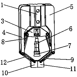
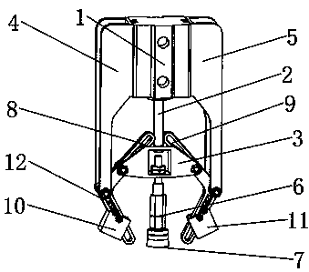
[0027] Embodiment 1: as Figure 1-9 As shown, the end effector of the film tearing robot includes cylinder 1, clamp finger movable mounting frame 3, clamp finger fixed mounting frame I4, clamp finger fixed mounting frame II5, vacuum adapter frame 6, vacuum suction cup 7, clamp finger I8, clamp Finger Ⅱ9, clamping block Ⅰ10, and clamping block Ⅱ11; the clamping finger fixed mounting frame Ⅰ4 and the clamping finger fixed mounting frame Ⅱ5 are installed on both sides of the cylinder 1 and fixedly connected, and the clamping finger movable mounting frame 3 is installed on the piston rod of the cylinder 1 2 The lower end, the upper ends of the clamp finger I8 and the clamp finger II9 are respectively connected to the two sides of the clamp finger movable mounting frame 3, and the middle parts of the clamp finger I8 and the clamp finger II9 are respectively installed on the clamp finger fixed mounting frame I4 and the clamp finger through the middle shaft hole. On the fixed install...

Embodiment 2

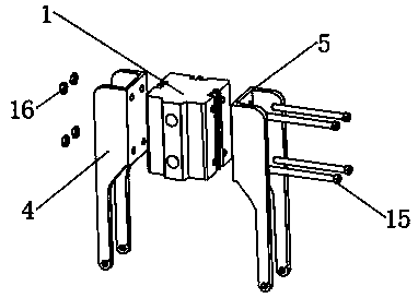
[0029] Embodiment 2: The device structure of this embodiment is the same as that of Embodiment 1, the difference is that the clamping block I10 or the clamping block II11 is fixedly connected with the slider 14 through the clamping block mounting shaft 23 and the clamping block mounting nut 24; the clamping fingers are fixedly installed Frame Ⅰ or finger fixing mounting frame Ⅱ is fixed on the cylinder 1 through the finger fixing shaft 15 and the finger fixing nut 16; on the mounting bracket 3.

[0030] When the above-mentioned device is in use, the cylinder 1 provides power for linear motion, and the vacuum adapter frame 6 connected to the piston rod 2 and the vacuum suction cup 7 at its lower end can realize up-and-down linear motion with the movement of the piston rod of the cylinder; When moving to the bottom, the vacuum suction cup generates an adsorption force to absorb the protective film on the surface of the product, and then moves up with the piston rod, the vacuum s...


PUM


Abstract

The invention discloses an end effector for a film tearing robot and belongs to the technical field of intelligent manufacturing of robots. The end effector comprises an air cylinder, a clamping finger movable mounting rack, a clamping finger fixed mounting rack I, a clamping finger fixed mounting rack II, a vacuum transfer rack, a vacuum chuck, a clamping finger I, a clamping finger II, a clamping block I and a clamping block II. When an air cylinder piston rod moves downwards, the vacuum chuck can tear up a protection film, when the air cylinder piston rod moves upwards, the clamping block Iand the clamping block II can clamp the torn film, and accordingly the protection film is torn apart. The end effector is high in practicability and good in performance, and manual film tearing can be replaced; the torn film can be a protection film of an electronic product, attachment films similar to a protection film for a glass plate and the like can also be torn apart, and the end effector is suitable for industrial production and application and popularization in the market.

Description

technical field [0001] The invention relates to an end effector of a film tearing robot, which belongs to the technical field of intelligent manufacturing robots. Background technique [0002] Protective films are commonly used in many links in the production of electronic products to protect the surface of electronic products from scratches and contamination; in the process of assembly and production, it is usually necessary to peel off the protective film first, but the protective film is often closely attached to the surface of electronic products , so it is more difficult to peel off the protective film. At present, most of the domestic and foreign electronic production industries still use manual labor to peel off the protective film. However, manual tearing of the film has many disadvantages. It not only wastes manpower but also has low production efficiency, and it is easy to pollute the surface of the component and reduce product quality. Contents of the invention ...

Claims


Application Information

Patent Timeline
Patent Type & Authority Applications(China)
IPC IPC(8): B25J15/08B25J15/06B65B69/00
CPCB25J15/08B25J15/06B65B69/0025
Inventor 王学军吴鹏伍星普江华马爱锋伞红军陈明方吴海波
Owner KUNMING UNIV OF SCI & TECH
Why Eureka
Try Eureka