Method for operating an anilox printing unit

A technology for printing devices and anilox rollers, applied to printing devices, general parts of printing machinery, printing, etc., can solve the problems of damaging the function of the blower device, polluting the blower device, etc.

Active Publication Date: 2008-06-11
海德堡印刷机械知识产权股份两合公司
View PDF2 Cites 7 Cited by
  • Summary
  • Abstract
  • Description
  • Claims
  • Application Information

AI Technical Summary

Problems solved by technology

In this ink supply system, the so-called doctor-type ink fountain, there is a danger when using the blower device of the prior art (DE 102 53 194 A1) described above: Ink detached from the underside drops onto the blower device and thus contaminates the blower device to the extent that its function is impaired

Method used


Image

  • Method for operating an anilox printing unit
  • Method for operating an anilox printing unit

Examples


Embodiment Construction

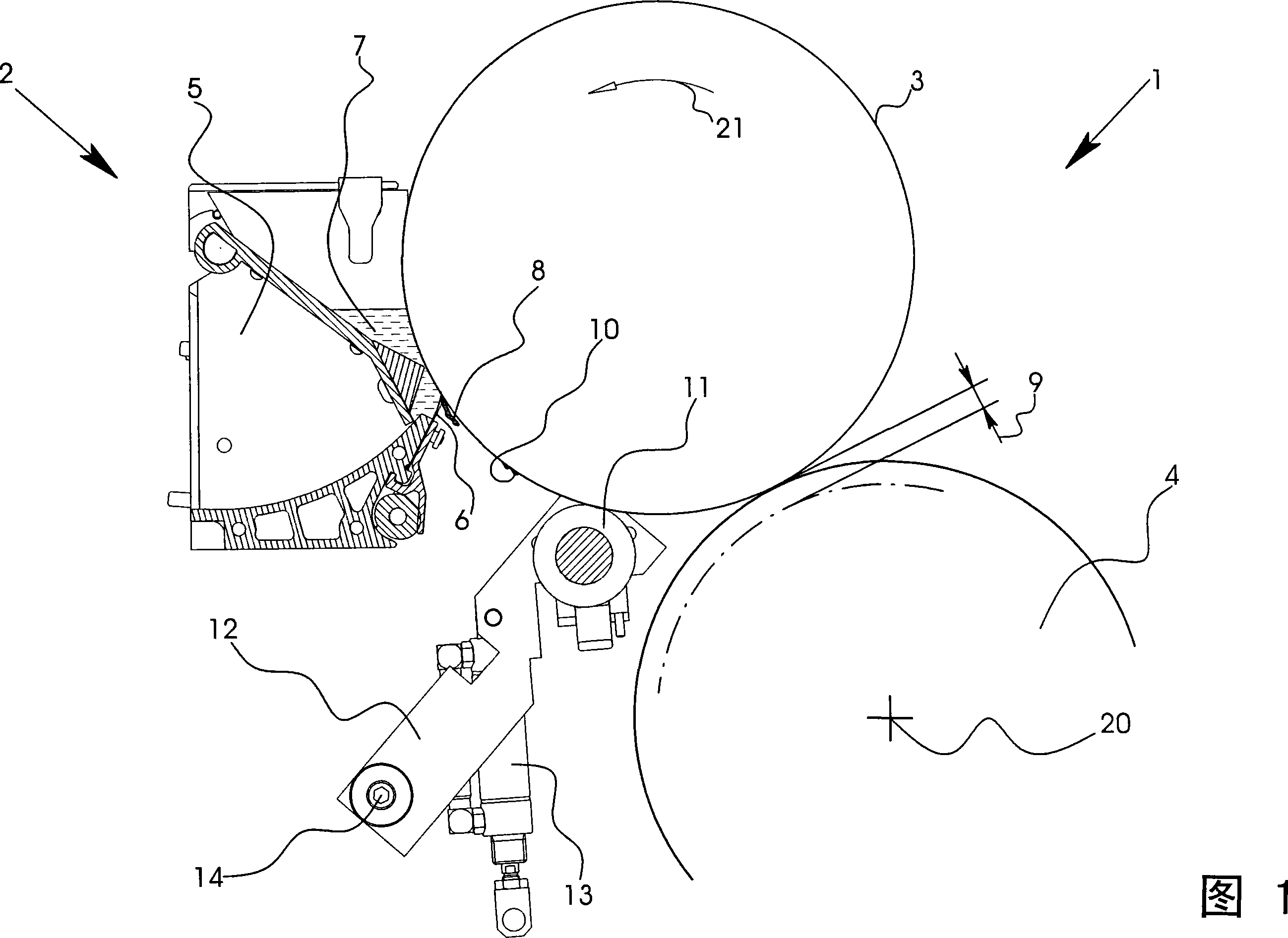
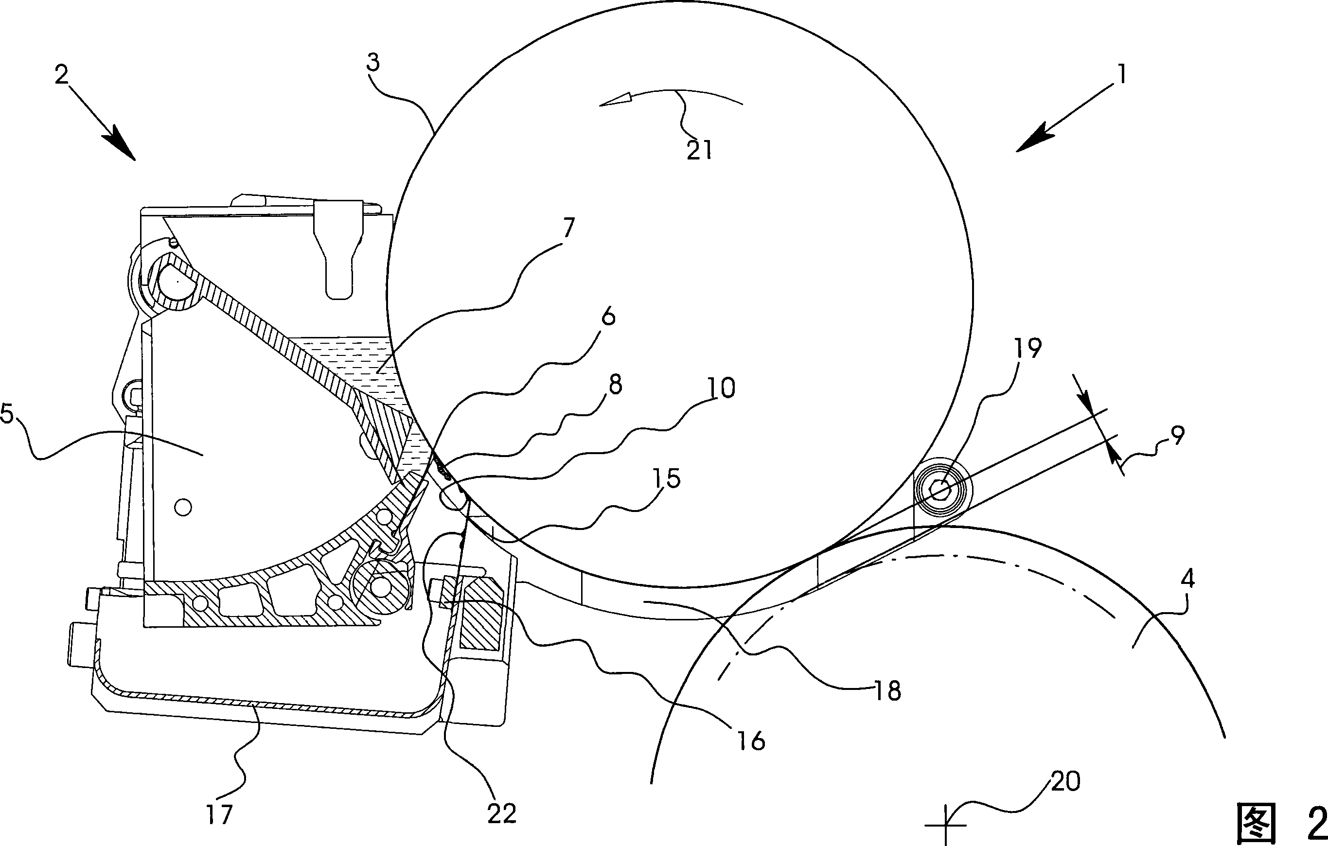
[0022] 1 and 2 each show a detail of a printing press 1 with an anilox printing unit 2 . The anilox printing unit 2 is an offset offset printing unit and comprises an anilox roll 3 and a further roll 4 onto which the anilox roll 3 transfers the printing ink. The other roller 4 is an ink form roller which rolls on a printing plate cylinder (not shown in the drawing) during the printing operation.

[0023] The screen roller 3 is equipped with an ink supply system in the form of an upwardly open doctor-type ink fountain 5 with a counter-working or supply doctor blade 6 . An ink supply 7 is located in the doctor-type ink fountain 5 . In the lower half of the screen roll 3 , the feed doctor blade 6 bears against the screen roll 3 in the region of its third quadrant.

[0024] Inevitably, over time, ink accumulates on the outside or underside of the feed doctor blade 6, which ink forms the so-called ink Must 8. When the screen roller 3 begins to rotate again at an increased speed...


PUM


Abstract

A method of operating an anilox printing unit (2) in which ink accumulates on and detaches from a feed blade (6) and, after detaching from the feed blade (6), forms ink accumulations (10) on a screen roller (3), and in which a gap (9) is formed between the screen roller (3) and a further roller (4) for the ink accumulations to pass through the gap without contacting the further roller (4). The method includes forming the gap (9) by displacing the axis of the further roller (4) and evening out the ink accumulations (10) on the screen roller (3) to such an extent that the ink accumulations (10) that have been evened out pass the gap (9) without contacting the further roller (4). A smoothing roller (11), for example, may be used to even out the ink accumulations (10).

Description

technical field [0001] The invention relates to a method for operating an anilox printing unit with ink that accumulates on and detaches from a feed doctor blade, wherein the ink is After the doctor blade is disengaged some ink conglomerates are formed on an screen roller, wherein a gap is formed between the screen roller and another roller through which the ink conglomerates pass without contacting the other roller. gap. Background technique [0002] Such a method is described in DE 102 53 194 A1. In this prior art method, the other roller has a circumferential clamping channel in which a clamping device for the embossed cloth is seated. Whenever, during the rotation of the further roller, the clamping channel is directed towards the screen roller, a roller gap through which ink conglomerates can pass is created between the screen roller and the further roller. The underside of the supply doctor blade forms together with the peripheral surface of the screen roller a wedg...

Claims


Application Information

Patent Timeline
Patent Type & Authority Applications(China)
IPC IPC(8): B41F31/04B41F31/20B41F31/02
CPCB41F35/04B41F31/20B41M1/12
Inventor G·宾德尔S·德米尔J·米歇尔斯D·沙夫拉特J·席尔法尔特W·舍恩贝格尔B·施瓦布M·蒂勒曼
Owner 海德堡印刷机械知识产权股份两合公司
Why Eureka
Try Eureka