Electric switching device comprising an arc-quenching unit

A technology of arc extinguishing device and electric switch, which is applied in the direction of electric switch, circuit, electric component, etc., can solve the problem of voltage loss increase, and achieve the effect of high switching capacity and low cost

Active Publication Date: 2008-11-19
KLOCKNER-MOELLER GMBH
View PDF7 Cites 1 Cited by
  • Summary
  • Abstract
  • Description
  • Claims
  • Application Information

AI Technical Summary

Problems solved by technology

In the case of arc division, the arc is magnetically driven into a system of parallel or arc-arranged arc chute and divided into partial arcs, which leads to a significant increase in the voltage loss within the entire arc

Method used


Image

  • Electric switching device comprising an arc-quenching unit
  • Electric switching device comprising an arc-quenching unit
  • Electric switching device comprising an arc-quenching unit

Examples


Embodiment Construction

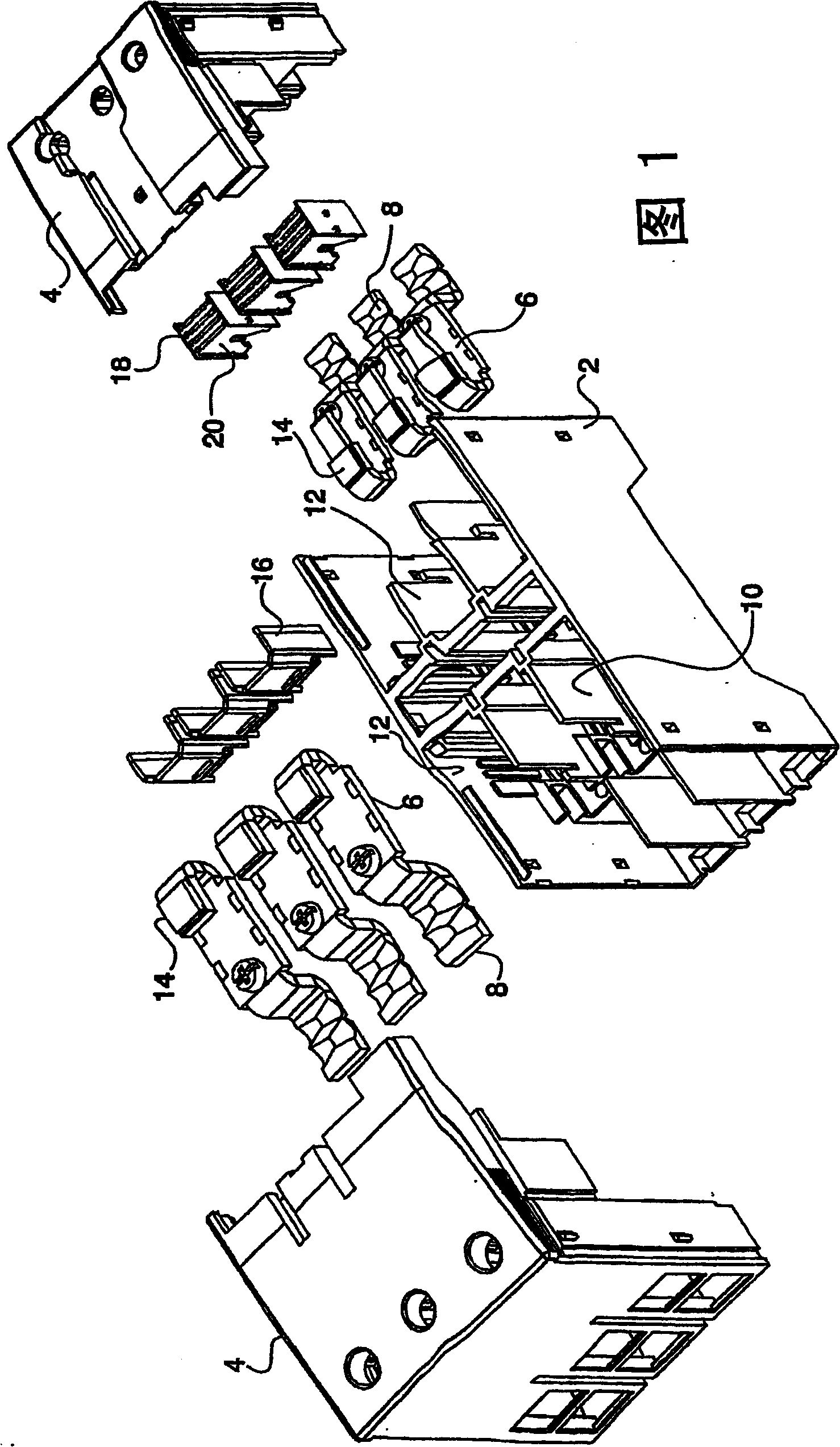
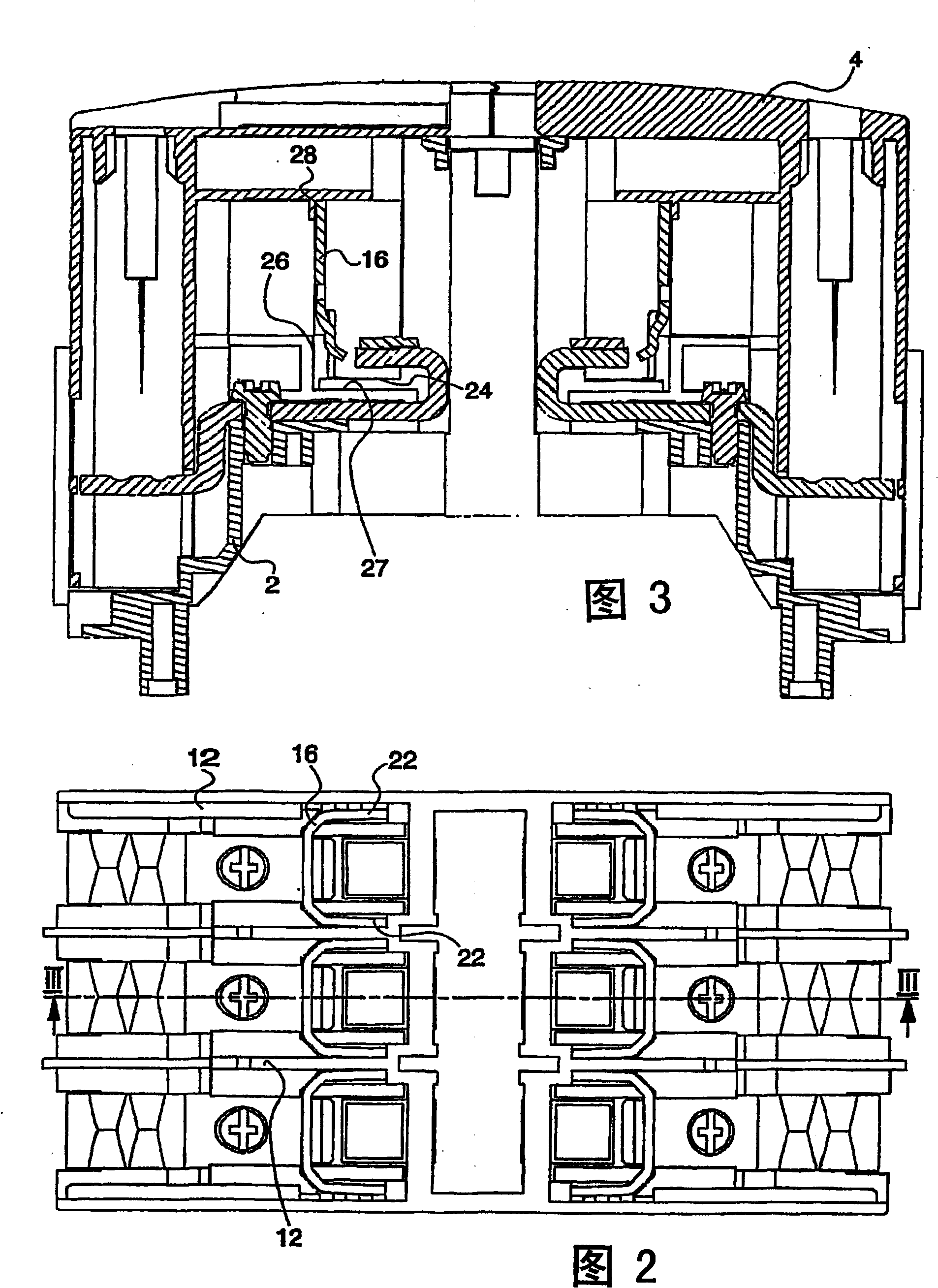
[0016] 1 shows the upper part of a multi-part housing 2 of an electrical switching device, for example a three-pole contactor, and a two-part cover 4 closing the housing 2 . Two busbars 6 with connecting contacts 8 accessible from the outside are provided per pole in the housing 2 . The busbars 6 protrude into switching chambers 10 which are bounded laterally by inner walls 12 formed in the housing 2 . On the switching chamber side, the contact rail 6 is provided with fixed switching contacts 14 which interact in a known manner with movable switching contacts in the form of non-illustrated contact bridges. In each switching chamber 10 an arc extinguishing device can be inserted, either in the form of a U-shaped cooling plate 16 or a set of arc extinguishing plates 20 stacked on top of each other at a distance 18 forms. For this purpose, guides and holders, which will be described in more detail below, are formed in the housing 2 and in the cover 4 . In each switching chambe...


PUM


Abstract

The related electric switch with arc extinguishing device comprises: in a shell (2) closed by a cover (4), a connection contact (8), some switch rooms (10) every with a fixed switch point (14) and a movable contact point and at least one arc-extinguishing device (16, 18); in (2) and (4), arranging some cooling plates (16), and the guide and hold members (12, 26, 28, 30) for arc-extinguishing plate assembly (18).

Description

technical field [0001] The invention relates to an electrical switching device designed for low voltages having at least one device for extinguishing an arc, in particular to a protective switch or a contactor. Background technique [0002] When large currents, in particular short-circuit currents, are switched off by the switching device, arcs form in its switching chamber. According to Franken, "Low-voltage power switches" ("Niederspannungs-Leistungsschalter"), Berlin, Heidelberg, New York, 1979, pp. 59-62, arc prolongation, arc cooling and arc division. In the case of arc cooling, intensive cooling of the arc is essentially achieved by contact with the insulating material piece or cooling plate. In the case of arc division, the arc is magnetically driven into a system of parallel or arcuately arranged arc quenching plates and divided into partial arcs, which leads to a considerable increase in the voltage loss within the entire arc. Cooling plates can be simpler and th...

Claims


Application Information

Patent Timeline
Patent Type & Authority Patents(China)
IPC IPC(8): H01H9/34H01H9/36H01H11/00
CPCH01H11/0006H01H9/362H01H9/36H01H2011/0093
Inventor 卡斯滕·格维格
Owner KLOCKNER-MOELLER GMBH
Why Eureka
Try Eureka