DEVICE AND METHOD FOR MOIRe MEASUREMENT OF AN OPTICAL TEST SPECIMEN

A technology for optical testing and equipment, applied in the field of equipment and methods for Moiré measurement of optical testing samples

Inactive Publication Date: 2018-10-23
CARL ZEISS SMT GMBH
View PDF4 Cites 0 Cited by
  • Summary
  • Abstract
  • Description
  • Claims
  • Application Information

AI Technical Summary

Problems solved by technology

[0008] However, a problem that actually occurs here is that, due to the angular distribution of the light emitted from the test object or the projection lens 6 or the moiré mask 8, things like Figure 16 The overlap of corresponding light cones assigned to different field points is shown ( Figure 16 denoted in "9a" and "9b"), the result is that in each case the light used to evaluate different field points partially coincides in the corresponding detection plane

Method used


Image

  • DEVICE AND METHOD FOR MOIRe MEASUREMENT OF AN OPTICAL TEST SPECIMEN
  • DEVICE AND METHOD FOR MOIRe MEASUREMENT OF AN OPTICAL TEST SPECIMEN
  • DEVICE AND METHOD FOR MOIRe MEASUREMENT OF AN OPTICAL TEST SPECIMEN

Examples


Embodiment Construction

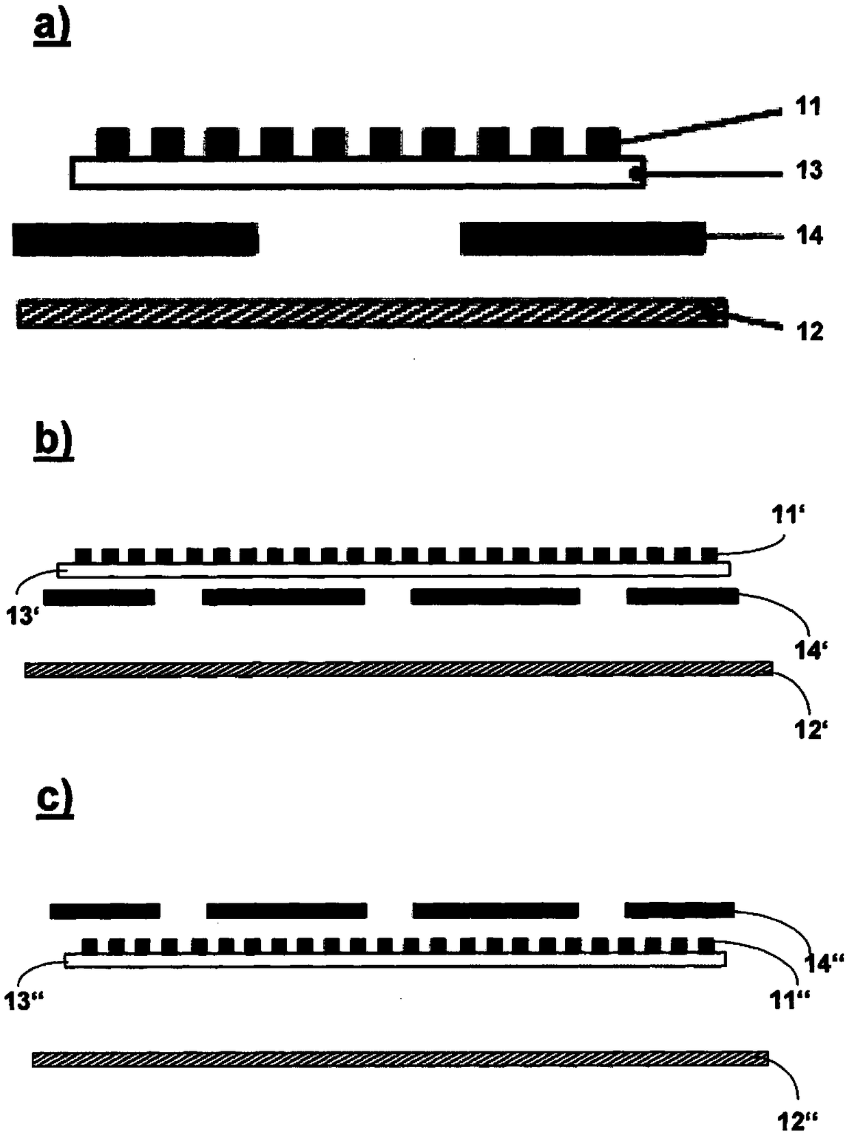
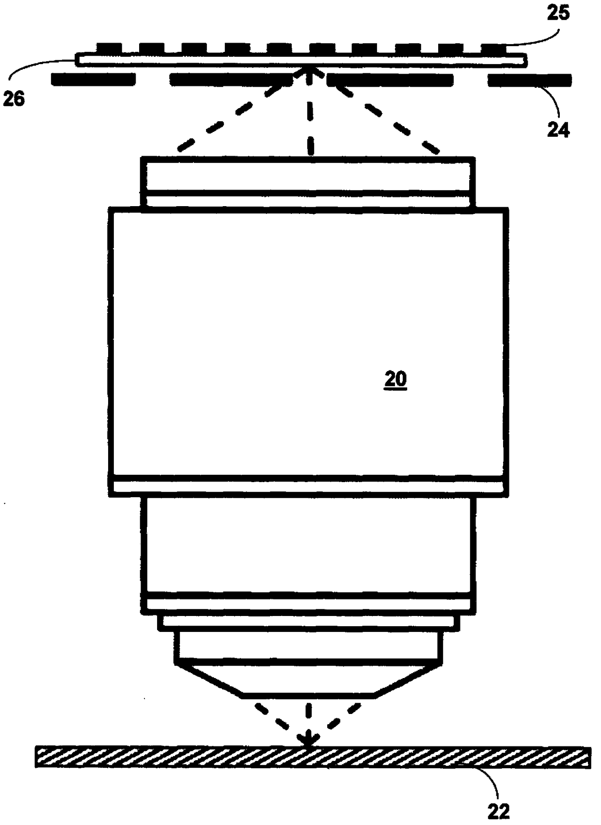
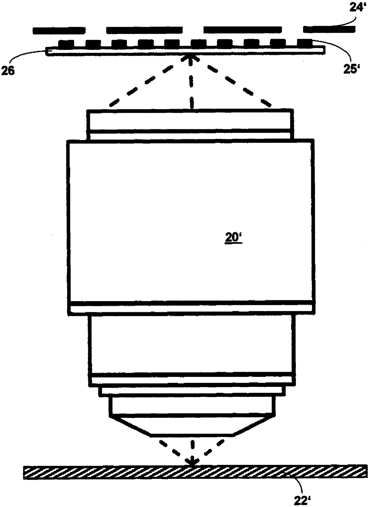
[0046] According to the present invention each figure 1 a-c provides aperture stop 14 (or figure 1 b and figure 1 c respectively 14' or 14"), the aperture stop 14 is laterally displaceable into different measuring positions along the direction of light propagation.

[0047] The resulting light distribution after the light emitted from the moiré mask or the second grating 11 can be shielded in a regionalized manner via the aperture stop 14, so that in each case only a subset of all field points reaches the detector 12 . The choice of measurable field points in the position of the aperture stop 14 can be such that light from different field points cannot be superimposed (where, for example, only every second, every third or every fourth field point). Capture of all field points on the moiré mask or on the second grating in a sequential measurement sequence can be achieved by displacing the aperture stop 14 into different measurement positions during successive measurement...


PUM


Abstract

The invention relates to a device for Moire measurement of an optical test specimen, comprising a grating arrangement composed of a first grating (25, 25', 35, 35'), which is positionable in the optical beam path upstream of the test specimen, and a second grating (11, 11', 11", 41, 51, 61, 71, 81, 91, 101, 111, 121, 131, 141), which is positionable in the optical beam path downstream of the testspecimen, an evaluation unit having at least one detector (12, 12', 12", 22, 22', 32, 32', 42, 52, 62, 72, 82, 92, 102, 112, 122, 132, 142) for evaluating Moire structures produced by superimpositionof the two gratings in a detection plane situated in the optical beam path downstream of the second grating, and at least one aperture stop (14, 14', 14", 24, 24', 34, 34'), by which the light distribution produced after emergence of light from the second grating can be shaded regionally in such a way that only light of a subset of all field points on the second grating reaches the detection plane.

Description

[0001] Cross References to Related Applications [0002] This application claims priority from German patent application DE 10 2016 202 198.2 of February 12, 2016. The content of this DE application is incorporated by reference into the text of the present application. technical field [0003] The present invention relates to apparatus and methods for moiré measurements of optical test samples. Background technique [0004] Microlithography is used to manufacture microstructural components such as integrated circuits or LCDs. The microlithographic process is performed in a so-called lithographic exposure apparatus that includes an illumination device and a projection lens. The image of the mask (= reticle) illuminated by the illumination device, in this case projected by a projection lens onto a substrate (e.g. silicon wafer) in order to transfer the mask structure to the photosensitive coating of the substrate. [0005] In practice, there is a need to determine imaging ...

Claims


Application Information

Patent Timeline
IPC IPC(8): G03F7/20G01M11/02
CPCG01M11/0242G03F7/706G03F7/0015G03F7/701G02B27/60G03B9/02
Inventor M.萨马涅戈P.谢德M.凯尔B.贾因克
Owner CARL ZEISS SMT GMBH
Why Eureka
Try Eureka