Screw drives for stroke-controlled compensating adjustments

A technology of compensation adjustment and stroke control, applied in the direction of mechanical drive clutches, friction clutches, clutches, etc., can solve problems such as screw nut warping, compensation adjustment device obstruction, etc., and achieve the effect of reducing friction

Active Publication Date: 2018-06-19
SCHAEFFLER TECH AG & CO KG
View PDF6 Cites 0 Cited by
  • Summary
  • Abstract
  • Description
  • Claims
  • Application Information

AI Technical Summary

Problems solved by technology

The tipping causes an increase in the friction between the spindle nut and the spindle drive or even warps the spindle nut and thus blocks the entire compensation adjustment

Method used


Image

  • Screw drives for stroke-controlled compensating adjustments
  • Screw drives for stroke-controlled compensating adjustments
  • Screw drives for stroke-controlled compensating adjustments

Examples


Embodiment Construction

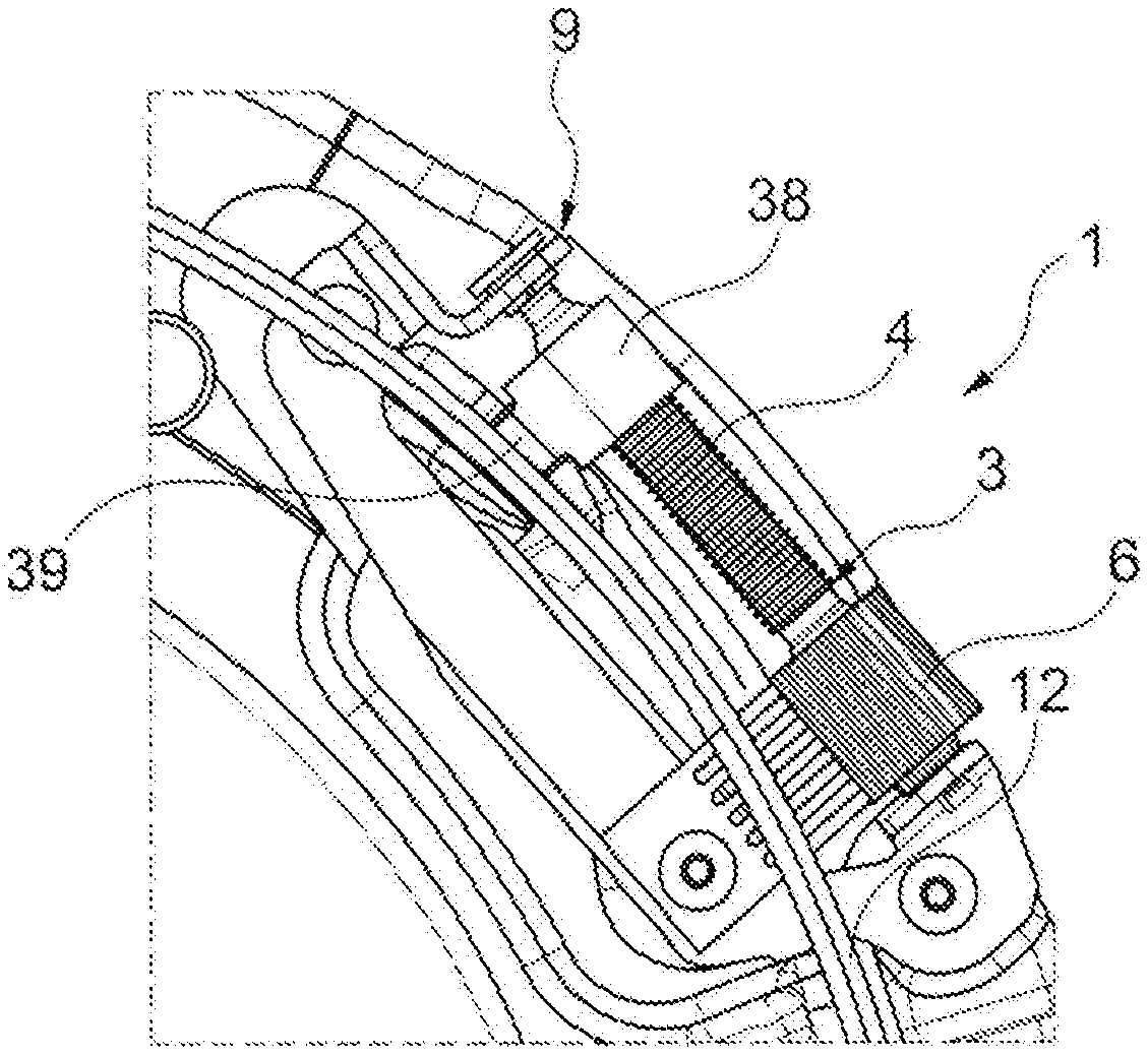
[0046] figure 1 A screw drive 1 is shown with a screw shaft 3 on which a worm drive 4 is arranged, which is driven by a drive pinion 6 . The spindle shaft 3 is received in the receptacle 9 and can thus be fastened to a component of the friction clutch. A conventional spindle nut 38 with a conventional transmission element 39 for compensating the adjusting ring 12 is arranged on the worm drive 4 . It is evident that, when the transfer element 39 is loaded, the spindle nut 38 can tilt and warp.

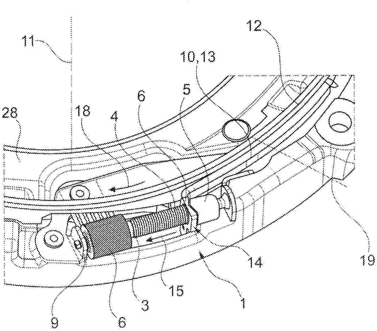
[0047] exist figure 2 The screw drive 1 in the receptacle 9 on the pressure plate 28 is shown in . Here, the screw shaft 3 with the worm drive 4 is twisted by driving the pinion 6 , so that the screw nut 5 is guided in the direction of movement 15 . The transmission element 10 , here embodied as a sheet-metal element 13 , is guided in the direction of movement 15 by the first flange 14 , so that the engaging compensating adjusting ring 12 in the compensating adjusting device 18 is ...


PUM


Abstract

The invention relates to a spindle drive for a path-controlled adjusting device, which has at least the following components: a spindle shaft having a worm gear drive; a spindle nut, which is translationally movable by means of the worm gear drive of the spindle shaft as a result of a torsion of the spindle shaft; a drive pinion for driving the spindle shaft; a drive pawl, which is fastenable to a coupling cover, for path-controlled driving of the drive pawl; a receptacle for the spindle shaft, which axially fastens the spindle shaft; and a transfer element which is designed to transfer the translational movement of the spindle nut to an adjusting ring, which is rotatable about a rotation axis aligned crosswise to the spindle shaft, wherein the transfer element comprises a plate element, which is tiltable around the rotation axis and via which, in assembly, the transfer force from the spindle nut on the adjusting ring can be applied centrally on the spindle nut. The transfer element according to the invention ensures an always central force application into a spindle nut, thus preventing a blocking of the adjusting device.

Description

technical field [0001] The invention relates to a screw drive for a stroke-controlled compensation adjustment device, in particular for a friction clutch of a motor vehicle. Background technique [0002] Spindle drives are known in the prior art, in which the spindle nut itself (on one side) fits directly into the compensation ring, whereby tipping of the spindle nut can occur. The tipping causes an increase in the friction between the spindle nut and the spindle drive or even warps the spindle nut and thus blocks the entire compensation adjustment. Contents of the invention [0003] Proceeding from this, the object of the present invention is based on at least partially overcoming the disadvantages known from the prior art. This object is solved by the features of the independent claims. Advantageous refinements are the subject matter of the subclaims. [0004] The invention relates to a screw drive for a stroke-controlled compensation adjustment device, said screw dri...

Claims


Application Information

Patent Timeline
Patent Type & Authority Patents(China)
IPC IPC(8): F16D13/75
CPCF16D13/757
Inventor M·芬肯策勒M·比尔克
Owner SCHAEFFLER TECH AG & CO KG
Why Eureka
Try Eureka