Cage-stabilizing and cage-locking device for cage of vertical shaft

A cage and tank stabilizing technology, applied in transportation and packaging, lifting equipment in mines, etc., can solve the problems of large up and down movement, achieve the effects of preventing slipping, reducing dynamic load, and simple structure

Inactive Publication Date: 2010-02-10
张金楼
View PDF0 Cites 35 Cited by
  • Summary
  • Abstract
  • Description
  • Claims
  • Application Information

AI Technical Summary

Problems solved by technology

[0009] The technical problem to be solved by the present invention is to overcome the technical defects existing in the prior art. In order to solve the problem of large vertical movement of the cage when loading deep wells and heavy equipment lifting tasks, the present invention provides a vertical shaft cage stabilizer and lock device for loading and unloading When loading and unloading, the cage is locked in a horizontal position to avoid sudden up and down movement of the cage due to elastic changes during loading and unloading, ensuring smooth loading and unloading. The dynamic load caused by unloading, and prevents the steel wire rope from slipping, prolonging the life of the steel wire rope and friction lining

Method used


Image

  • Cage-stabilizing and cage-locking device for cage of vertical shaft
  • Cage-stabilizing and cage-locking device for cage of vertical shaft
  • Cage-stabilizing and cage-locking device for cage of vertical shaft

Examples


Embodiment Construction

[0016] The present invention will be described in further detail below in conjunction with the accompanying drawings and embodiments.

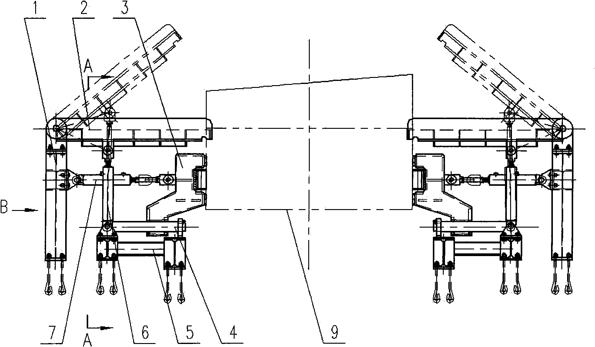
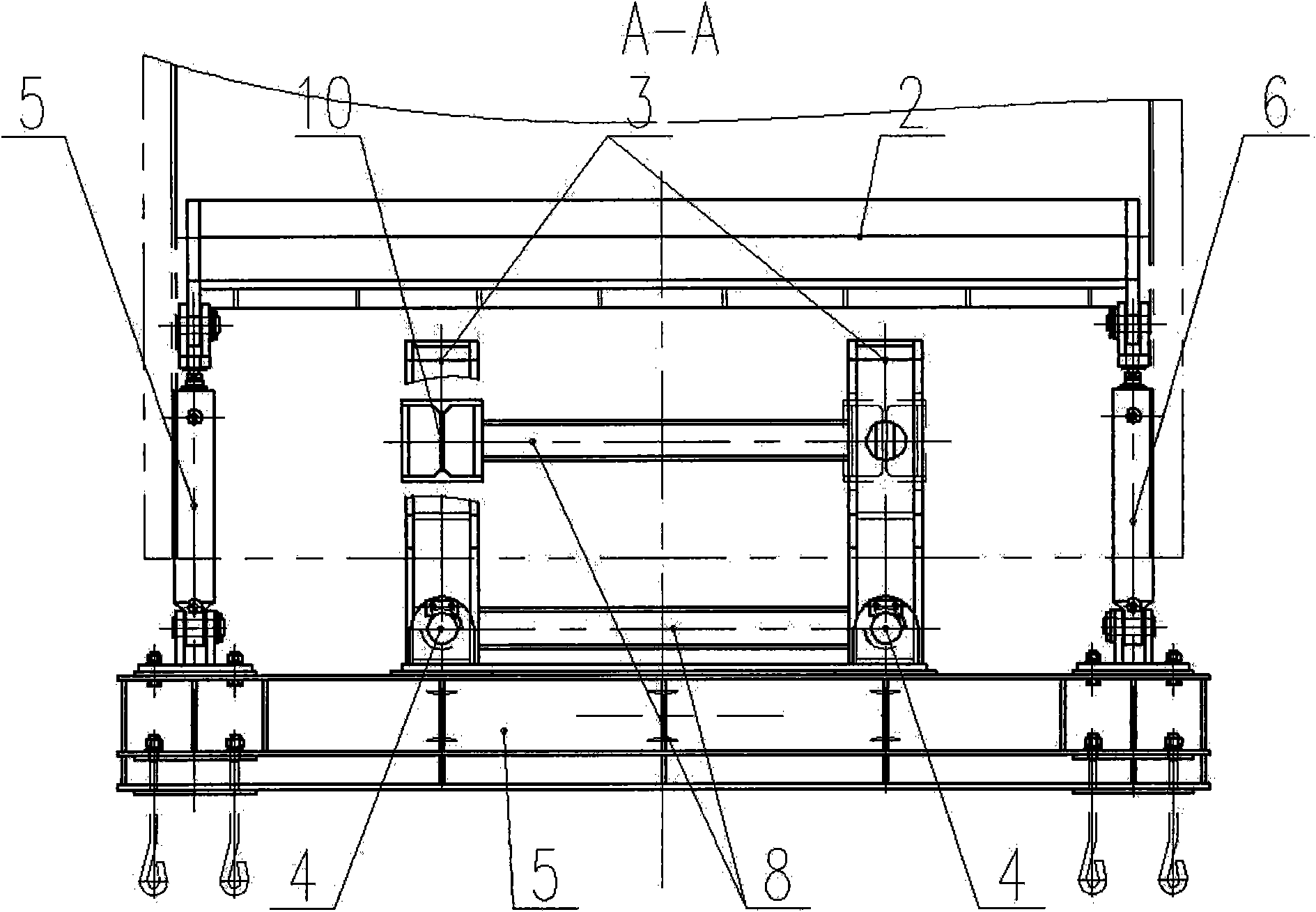
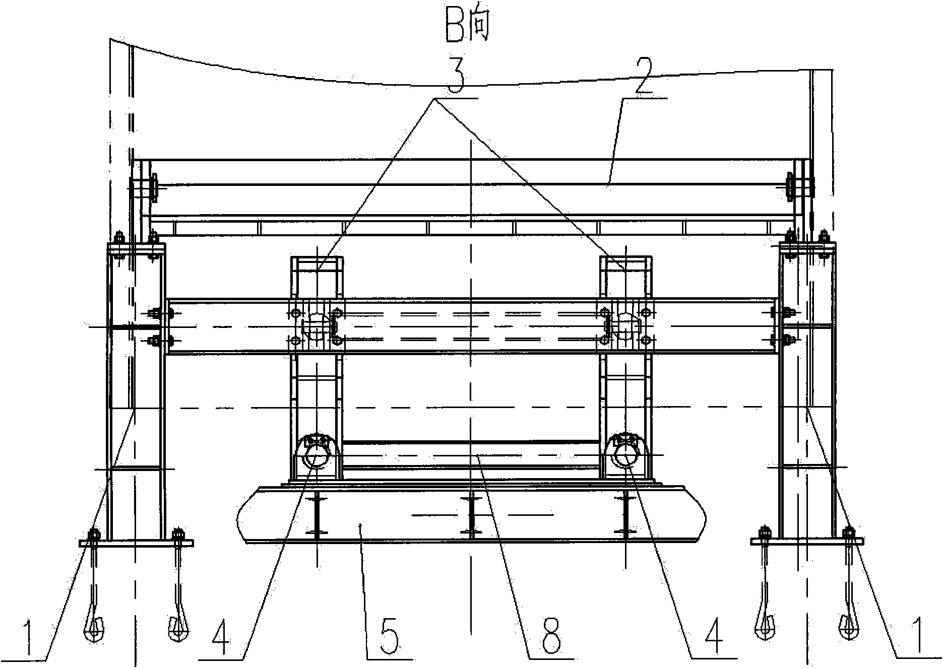
[0017] The shaft cage cage stabilizer and lock device consists of a support 1 (1), a swing platform (2), a can clamping device (3), a guide device (4), a support 2 (5), a swing hydraulic cylinder or cylinder (6), Direct push hydraulic cylinder or air cylinder (7) form. It is characterized in that: the swing platform (2) is hinged to the support 1 (1), and the swing hydraulic cylinder or cylinder (6) is respectively hinged to the swing platform (2) and the support 2 (5); the direct push hydraulic cylinder or cylinder (7 ) is respectively hinged with the canister device (3) and the support 1 (1); the guide device (4) is connected with the support 2 (5) with a spring.

[0018] The vertical shaft cage cage stabilizer tank lock device is symmetrically arranged by the above two sets of tank lock devices, which are respectively arranged on the entra...


PUM


Abstract

The invention discloses a cage-stabilizing and cage-locking device for a cage of a vertical shaft. The device consists of a first supporting seat (1), an oscillating platform (2), a cage-clipping device (3), a guiding device (4), a second supporting seat (5), an oscillating hydraulic cylinder or air cylinder (6) and a straight push hydraulic cylinder or air cylinder (7). The device is characterized in that: the oscillating platform (2) is hinged with the first supporting seat (1), and the oscillating hydraulic cylinder or air cylinder (6) is hinged with the oscillating platform (2) and the second supporting seat (5) respectively; the straight push hydraulic cylinder or air cylinder (7) is hinged with the cage-clipping device(3) and the first supporting seat (1) respectively; and the guiding device (4) and the second supporting seat (5) are connected by a spring. The cage-stabilizing and cage-locking device of the invention comprises two sets of cage-locking devices symmetrically arranged, and the forward and backward movements of the cage-clipping device are realized by the guiding device (4) and the straight push hydraulic cylinder or air cylinder (7). The device of the inventionhas a simple structure and can be conveniently assembled and tuned; and by using the device, the cage can be locked when assembled or disassembled, so that the cage is prevented from swaying up and down due to elastic change when being assembled and disassembled, and the stable assembly and disassembly of the cage is ensured. The device has the advantages of preventing skid of a wire cable, reducing the elastic deformation of the wire cable, and prolonging life time of the wire cable and the friction lining.

Description

Technical field [0001] The invention relates to equipment in a mine shaft hoisting system, and relates to a tank stabilizing device used for hoisting a mine shaft cage to prevent the cage from moving too much up and down to affect normal loading and unloading, especially suitable for cage lifting in deep shafts and heavy equipment shafts used in . Background technique [0002] The commonly used cage receiving devices in vertical shaft cage lifting include cradle, tank supporting machine, self-compensating tank supporting cradle, conversion platform (foreign product), a tank stabilizing mechanism and tank stabilizing device for vertical shaft cage lifting. [0003] The tank supporting machine has a large adjustment distance, which can be used in deep wells and large wells, and is specially used for multi-rope hoists, but it requires that the cage must have a separate movable chassis, which makes the structure of the cage more complicated and heavy; at the same time, it takes ...

Claims


Application Information

Patent Timeline
Patent Type & Authority Applications(China)
IPC IPC(8): B66B17/16B66B17/00
Inventor 张金楼姬红刚李刚马宪胜杨晓席海涛秦博田颖郝国花黄博华
Owner 张金楼
Why Eureka
Try Eureka