
Frame for multiple vehicle heat exchangers

a technology for heat exchangers and frames, which is applied in the direction of machine supports, machines/engines, light and heating apparatus, etc., can solve the problems of difficult connection of heat exchangers to prior art frames, interference with the flow of cooling air, and difficult air flow across the entire heat exchange surfa

Inactive Publication Date: 2006-10-17
MODINE MFG CO
View PDF6 Cites 20 Cited by
  • Summary
  • Abstract
  • Description
  • Claims
  • Application Information

AI Technical Summary

Benefits of technology

[0009]In one aspect of the present invention, a frame adapted to support a plurality of heat exchangers one in front of another in the direction of flow of cooling air is provided, where at least one of said heat exchangers is generally box shaped with projecting components on opposite sides thereof. The frame includes two vertical walls interconnected at upper and lower ends by two transverse walls, cross braces between the walls, and fastening points o

Problems solved by technology

Further, in many applications, strength requirements necessitate the inclusion of braces across the frame, which braces can interfere with the flow of cooling air through the supported heat exchangers.
Still further, particularly with rectangular frames, air flow across the entire heat exchange surfaces has been difficult to achieve.
The connection of heat exchangers to such prior art frames has, moreover, been difficult.
On the one hand, particularly when used, for example, in vehicular applications, the entire assembly will be subject to frequent vibrations and other similar changing loads, necessitating that a rigid, secure connection between the frame and the heat exchangers be provided.
On the other hand, desirable rapid and simple assembly and disassembly of the heat exchangers has been difficult to achieve while still providing a structure which will provide a reliable support over long periods of time notwithstanding vibrations and changing loads, and further notwithstanding the need to prevent or suppress clattering noises potentially caused by vibrations.

Method used


Image

  • Frame for multiple vehicle heat exchangers
  • Frame for multiple vehicle heat exchangers
  • Frame for multiple vehicle heat exchangers

Examples


Embodiment Construction

[0028]Various aspects of the invention are included in the single embodiment illustrated in the figures.

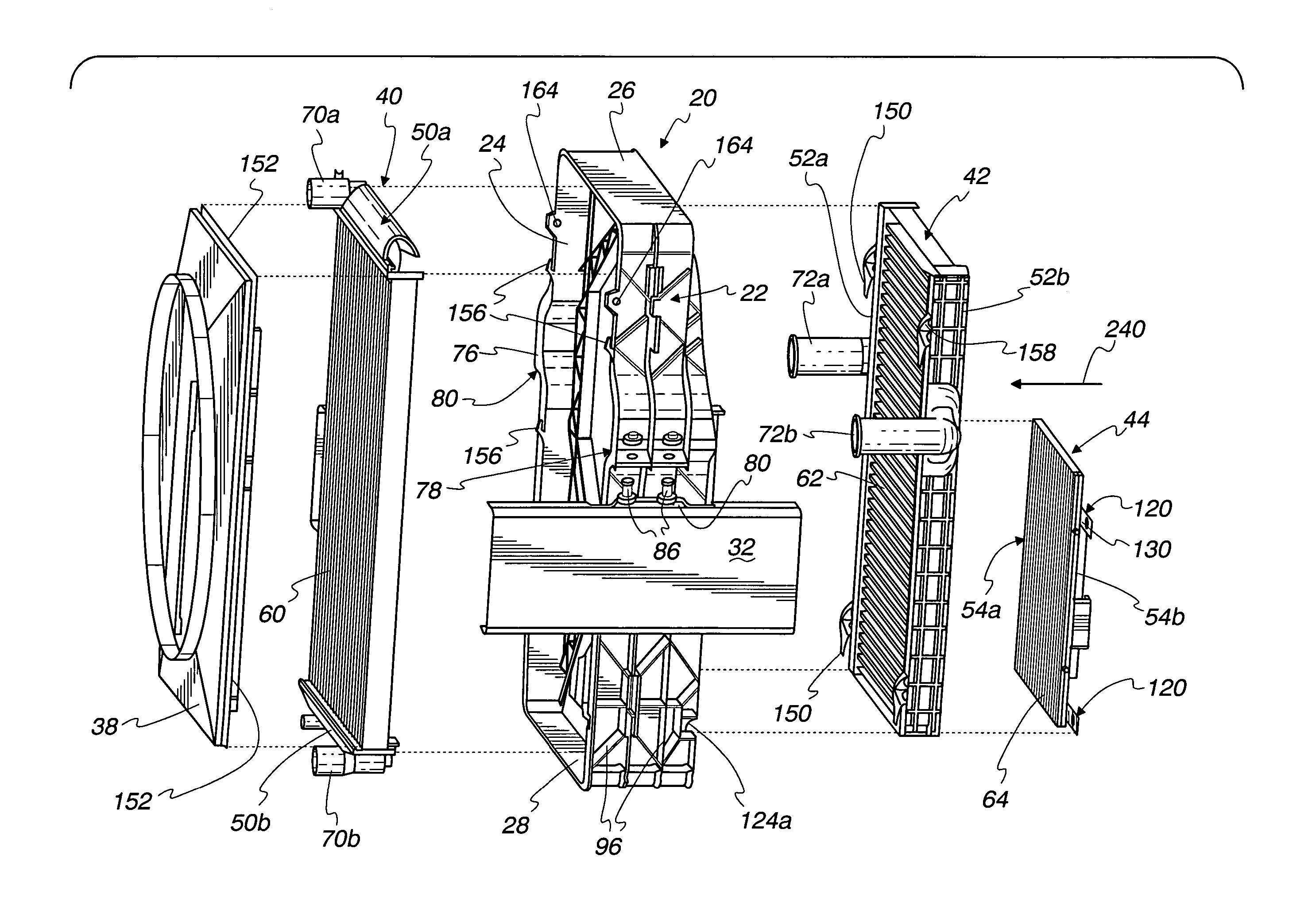
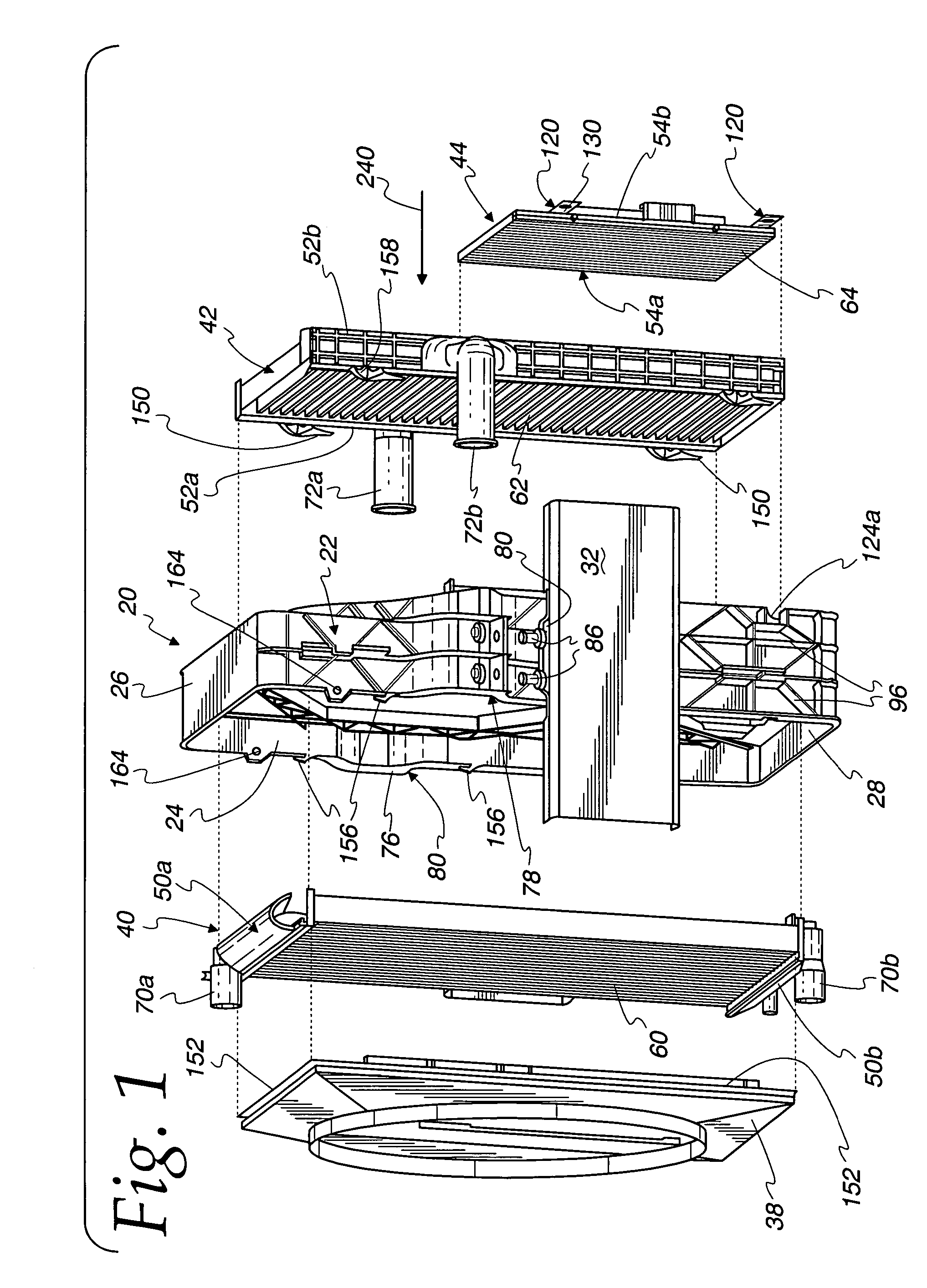
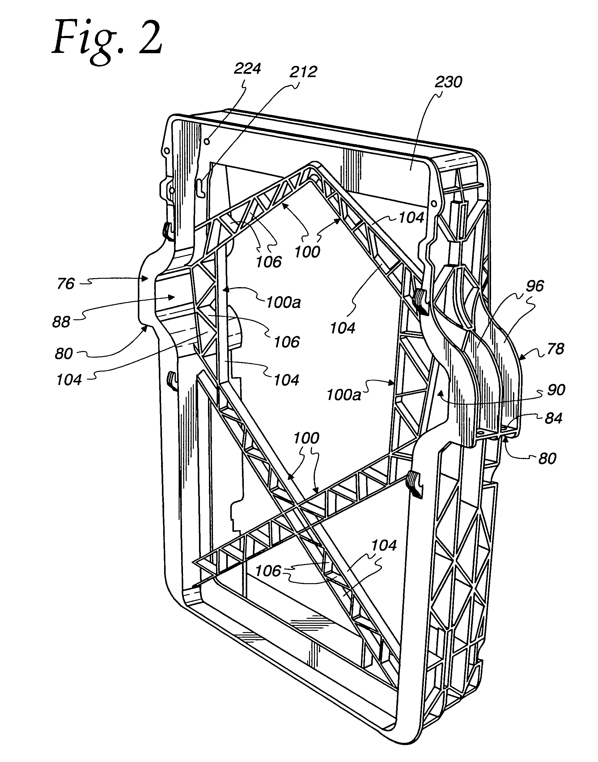
[0029]A frame 20 for supporting a plurality of heat exchangers is illustrated in the drawings. Particularly in FIG. 1, it can be seen that the frame 20 consists of two vertical (side) walls 22, 24, interconnected at upper and lower ends by top and bottom transverse walls 26, 28. The transverse walls 26, 28 are shorter than the vertical walls 22, 24, although it should be understood that they could alternatively be the same length as, or longer than, the vertical walls 22, 24 within the scope of the invention. In a vehicle, for example, the vertical walls 26, 28 may be supported on frame body members 32 (see FIG. 1), with the transverse walls 26, 28 arranged in the transverse direction of the vehicle.

[0030]A fan shroud 38 may be provided at one end of the structure, for example, behind the heat exchanger arrangement viewed in the direction of travel of the vehicle, whereby a fan as...


PUM


Abstract

A frame supports heat exchangers one in front of another in the direction of flow of cooling air, and includes two vertical walls interconnected by transverse walls, cross braces between the walls, and fastening points on the walls adapted to fasten the heat exchangers to the frame. Outwardly extending bulging sections in the vertical walls include an outer portion adapted to be secured to the vehicle support members to support the frame thereon, and an inner portion defining a space between vertical wall sections above and below the bulging section for receive projecting components of at least one heat exchanger. Connectors connect each of the fastening openings to the aligned flange openings, with the connectors including a head and a stem with an expandable end opposite the head retaining the connectors in the aligned openings. Hooks support the heat exchangers in the direction of air flow, with the connector stems supporting against at least some forces transverse to the direction of air flow.

Description

CROSS REFERENCE TO RELATED APPLICATION(S)[0001]Not applicable.STATEMENT REGARDING FEDERALLY SPONSORED RESEARCH OR DEVELOPMENT[0002]Not applicable.REFERENCE TO A MICROFICHE APPENDIX[0003]Not applicable.TECHNICAL FIELD[0004]The present invention is directed toward heat exchangers for vehicles, and particularly toward a supporting frame for multiple heat exchangers used with vehiclesBACKGROUND OF THE INVENTION AND TECHNICAL PROBLEMS POSED BY THE PRIOR ART[0005]In many different applications, a plurality of heat exchangers are used with one or more systems present in the application. Particularly in vehicular applications, for example, it is desirable to minimize the size and weight of the heat exchangers and their supporting structure.[0006]Therefore, frames have been provided which support a number of different heat exchangers together in a relatively compact space, and in an environment where air flows advantageously over all of the heat exchangers to provide advantageous, required h...

Claims


Application Information

Patent Timeline
IPC IPC(8): B60K11/04F28D1/04F28F9/00F28F9/013
CPCB60K11/04F28D1/0435F28F9/002F28F9/013F01P2070/50
Inventor BECK, RALFNITSCHE, WERNERSTRAHLE, ROLANDNIES, JENSROCKENFELLER, HEINRICHBITTNER, WILFRIED
Owner MODINE MFG CO
Learn More