
Tool body and cutting insert for metal cutting operations

a cutting tool and insert technology, applied in the field of cutting tools, can solve problems such as damage to the cutting surface of workpieces

Inactive Publication Date: 2006-10-17
KENNAMETAL INC
View PDF13 Cites 15 Cited by
  • Summary
  • Abstract
  • Description
  • Claims
  • Application Information

AI Technical Summary

Benefits of technology

[0006]The invention is further directed to a cutting tool, as summarized above, having a cutting insert held within the pocket by a clamping screw that is adapted to be inserted through the first portion of the tool

Problems solved by technology

Chips are often deposited on the workpiece and subsequently re-cut by the cutting inserts, resulting in damage to the cut surface of the workpiece.

Method used


Image

  • Tool body and cutting insert for metal cutting operations
  • Tool body and cutting insert for metal cutting operations
  • Tool body and cutting insert for metal cutting operations

Examples


Embodiment Construction

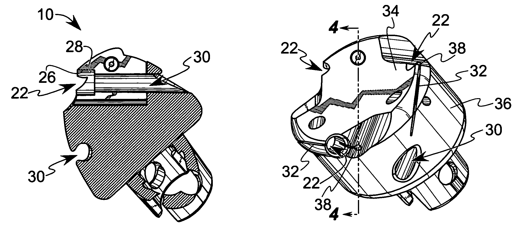
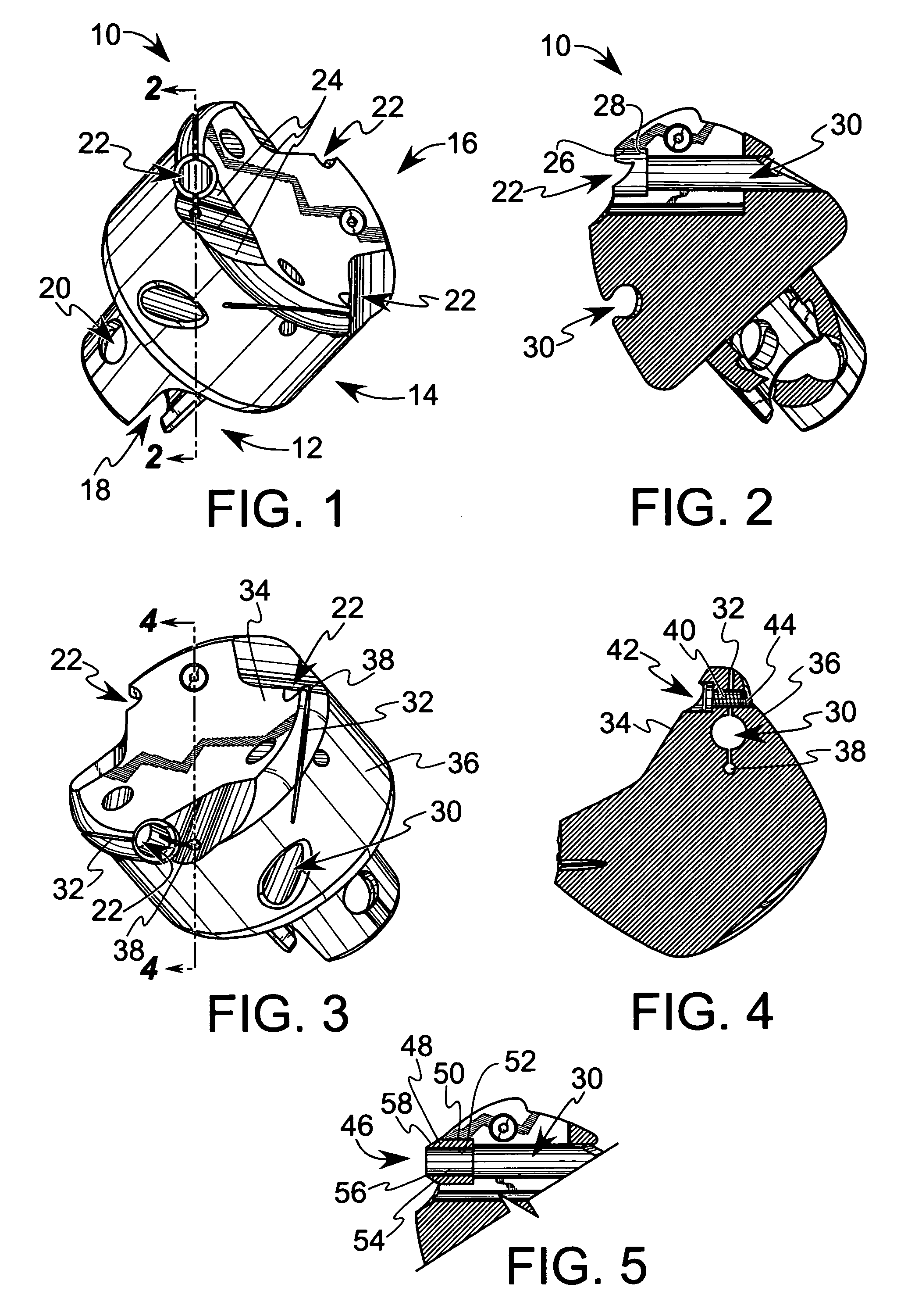
[0020]With reference now to the drawings, wherein like numerals designate like components throughout all of the several figures, there is illustrated in FIG. 1 a tool body 10 having shank 12, which is adapted to be supported by a metal cutting machine, a generally cylindrical portion 14, and a working end 16, which is adapted to support one or more cutting inserts.

[0021]The shank 12 shown is a hollow taper shank, which is particularly suitable for high-speed operations. It includes a relief 18, which allows for expansion of the shank 12 when inserted into the cutting machine, and two holes 20 that are engaged by balls in the cutting machine to pull the shank 12 therein. It should be understood that the tool body 10 may employ other shanks and though the tool body 10 is well suitable for high-speed metal cutting operations, the tool body 10 may be suitable for other metal cutting operations.

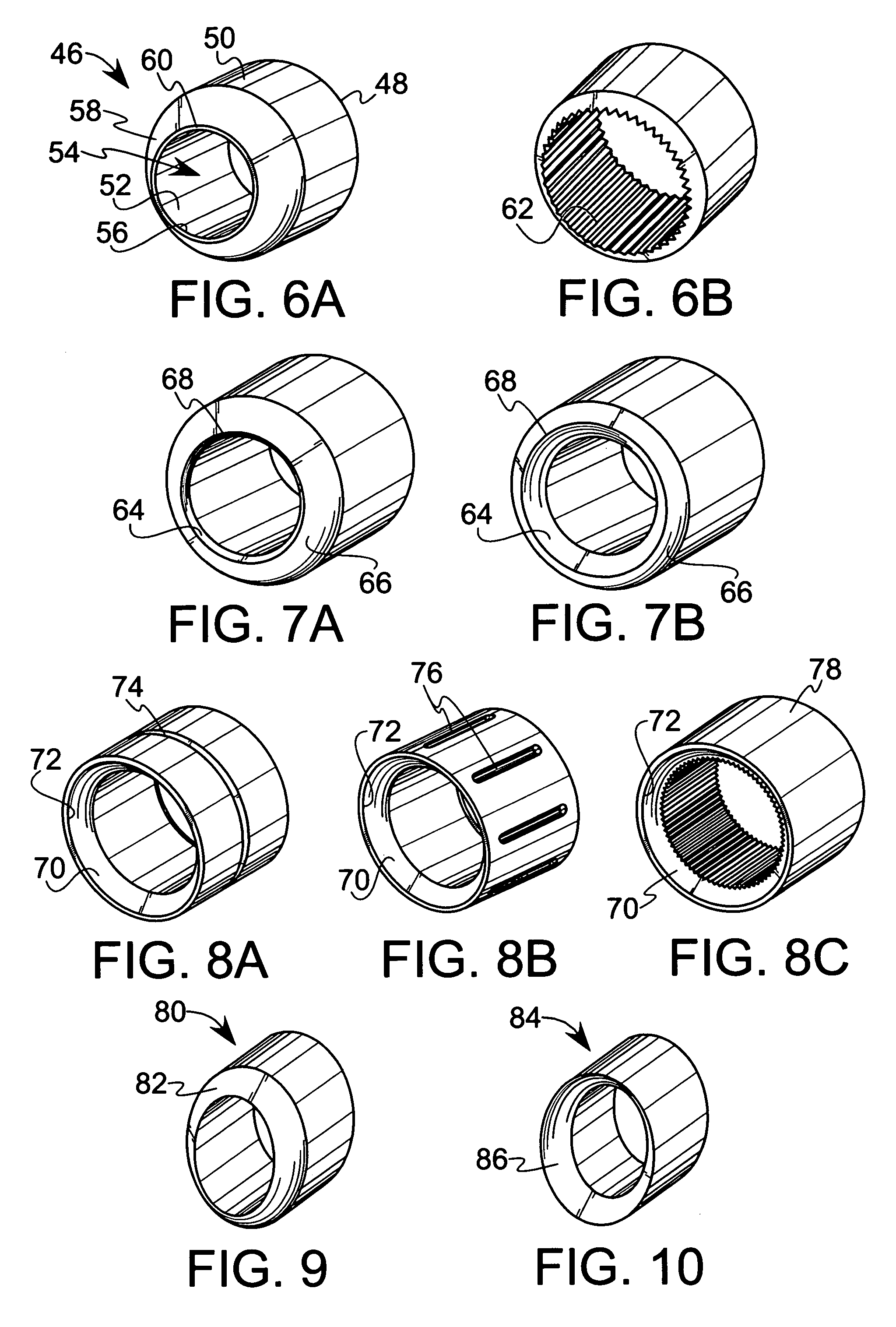
[0022]The working end 16 has one or more pockets 22 therein for supporting the cutting inserts...


PUM

PropertyMeasurementUnit
Lengthaaaaaaaaaa

Abstract

A cutting tool body that is adapted for use in milling operations comprises at least one pocket for supporting a cutting insert. The pocket is defined, at least in part, by a cylindrical wall and a seating surface within the tool body. At least one passage is provided through the tool body for evacuating chips upward and away from the surface of a workpiece. The seating surface of the pocket extends radially inward from the cylindrical wall and intersects the passage through the tool body. At least one slot traverses the pocket to separate a part of the tool body into first and second portions, at least one of which is movable relative to the other for clamping the cutting insert into the pocket.

Description

BACKGROUND OF THE INVENTION[0001]The present invention relates in general to cutting tools and, more particularly, to a tool body and inserts that are especially suitable for use in metal cutting operations.[0002]Cutting tools for metal cutting operations are well known. A conventional metal cutting tool typically comprises a tool body that is adapted to mate with a cutting machine. The tool body has a working end and one or more pockets in the working end. A conventional pocket ordinarily includes a floor and two seating surfaces. The pockets are provided for receiving cutting inserts. A retention screw threaded into a threaded hole in the tool body holds the insert in the pocket.[0003]Conventional metal cutting tools are adapted for use in removing material from a metal workpiece. The material removed is commonly referred to as a chip. Chips are often deposited on the workpiece and subsequently re-cut by the cutting inserts, resulting in damage to the cut surface of the workpiece....

Claims


Application Information

Patent Timeline
IPC IPC(8): B23C5/10
CPCB23C5/109B23C5/22B23C2200/045B23C2200/365B23C2210/16Y10T407/192B23C2210/50B23C2230/045Y10T407/19Y10T407/1908B23C2210/161
Inventor GAMBLE, KEVIN M.LONG, II, THOMAS J.
Owner KENNAMETAL INC
Learn More