Weight-training apparatus having selectable weight plates

a technology of weight plates and weight training, which is applied in the field of weight training equipment, can solve the problems of large machines and equipment, cumbersome and time-consuming, and large machines and equipmen

Active Publication Date: 2006-10-17
BOWFLEX INC
View PDF20 Cites 74 Cited by
  • Summary
  • Abstract
  • Description
  • Claims
  • Application Information

AI Technical Summary

Problems solved by technology

Typically, these machines and apparatuses are large and bulky and may require a number of heavy weight plates as well as large frames, cables, and pulleys for their proper use.
These machines and apparatuses are so large, in fact, that many of them are found only in health and fitness clubs.
While weight plates can be adequately secured to the bar in this manner, users find the securement means to be rather cumbersome and time consuming, especially when having to change weight plates multiple times, to a point where some users omit the collars during an exercise, preferring to risk losing a weight plate from the bar and damaging property or, much worse, causing injury.
While this is quicker than changing weight plates, storing a number of differently weighted dumbbells for personal use is inefficient and impractical.
While a commercial embodiment of the '997 patent addresses the concerns associated with the prior ways of exercising with dumbbells, the maximum weight of the dumbbell pairs of that commercial embodiment is limited to only 30 pounds for each dumbbell.
This dumbbell is too large and cumbersome even for the most experienced weight trainers.
When performing certain exercises that require two dumbbells to be used at the same time, side-by-side and lengthwise, weight trainers find the prior art dumbbells to be uncomfortable and cumbersome because they are too long and bulky.
Thus, weight trainers are unable to maximize their training efforts.

Method used


Image

  • Weight-training apparatus having selectable weight plates
  • Weight-training apparatus having selectable weight plates
  • Weight-training apparatus having selectable weight plates

Examples


Embodiment Construction

[0026]Referring now to the drawings, preferred illustrative embodiments of the present invention are shown in detail. Although the drawings represent embodiments of the present invention, the drawings are not necessarily to scale and certain features may be exaggerated to better illustrate and explain the present invention. Further, the embodiments set forth herein are not intended to be exhaustive or otherwise to limit or restrict the invention to the precise forms and configurations shown in the drawings and disclosed in the following detailed description.

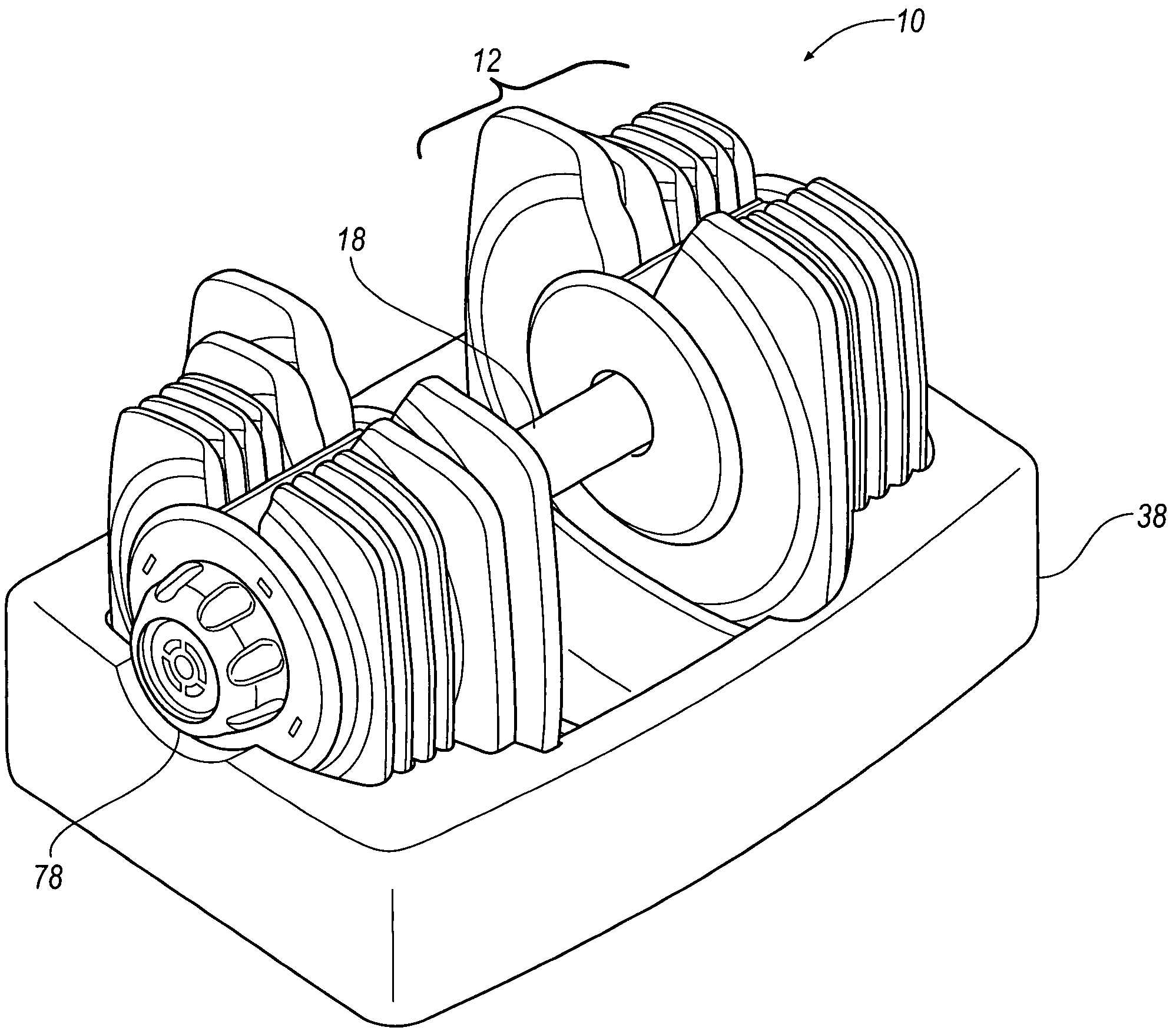
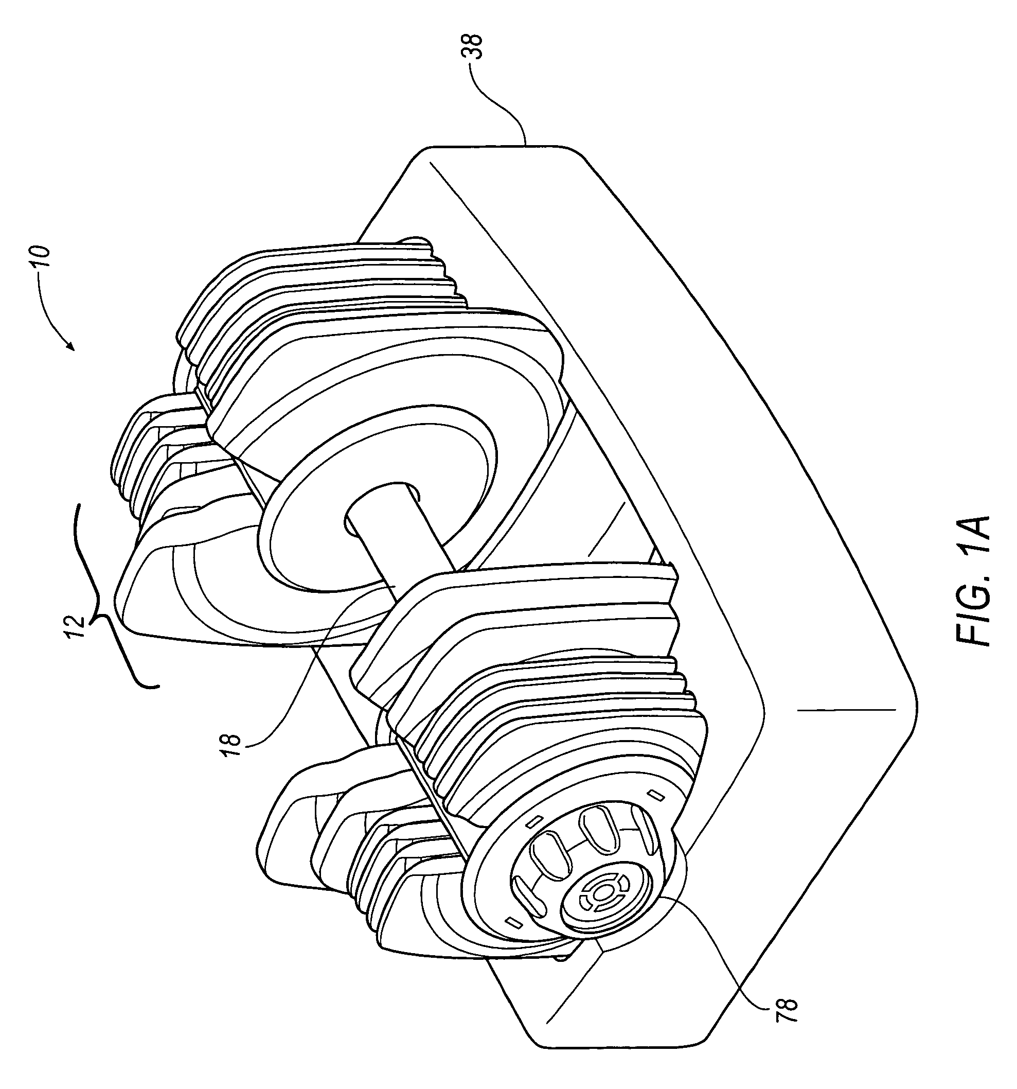
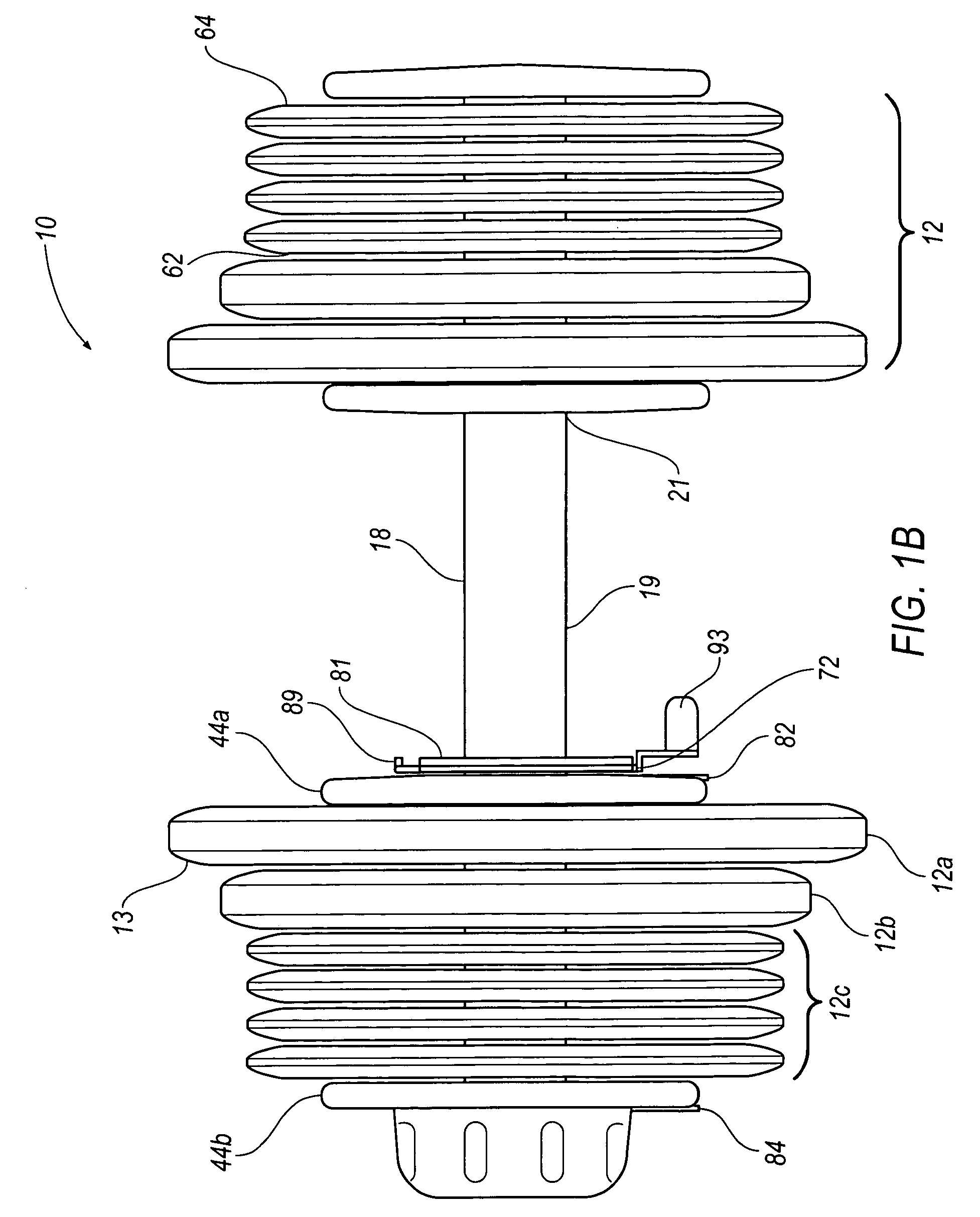
[0027]FIG. 1A illustrates a weight-training apparatus 10 and holder 38 according to an embodiment of the present invention. FIG. 1B illustrates a side view of weight-training apparatus 10 of FIG. 1A that is commonly used by people for regularly exercising their bodies to tone and develop various muscle groups in an effort to enhance their physical attributes and to maintain good health. In this particular embodiment, weight-train...


PUM


Abstract

An adjustable weight-training apparatus is provided having a plurality of weight plates, each of the weight plates including a protrusion. The weight-training apparatus has longitudinally opposing ends, each of the ends having longitudinally outer and inner groups of weight plates. A rotatable bar is also included in the apparatus and includes an inner control shaft and an outer control shaft. The inner control shaft is configured to rotate within the outer control shaft. The rotatable bar is configured to rotate within central holes of the weight plates. The inner control shaft has a first plurality of longitudinally spaced lobes. The inner control shaft is rotatable to position selected ones of the first plurality of lobes in engagement with the protrusions of selected weight plates of at least one of the outer groups of weight plates. The outer control shaft has a second plurality of longitudinally spaced lobes. The outer control shaft is rotatable to position selected ones of the second plurality of lobes in engagement with the protrusions of selected weight plates of at least one of the inner groups of weight plates.

Description

FIELD OF THE INVENTION[0001]The present invention relates generally to weight-training apparatuses and machines and, more particularly, to a weight-training apparatus having a pair of mechanisms for selecting and locking a plurality of self-contained weight plates to a bar.BACKGROUND OF THE INVENTION[0002]Weight training is a popular physical fitness activity for aiding in the maintenance of one's overall physical health. A variety of weight-training exercises may be accomplished by employing any number of machines or apparatuses. Typically, these machines and apparatuses are large and bulky and may require a number of heavy weight plates as well as large frames, cables, and pulleys for their proper use. These machines and apparatuses are so large, in fact, that many of them are found only in health and fitness clubs. However, variations of these larger machines and apparatuses have been redesigned and adapted for home use.[0003]One such apparatus is the dumbbell. In the past, there...

Claims


Application Information

Patent Timeline
Patent Type & Authority Patents(United States)
IPC IPC(8): A63B21/072A63B21/062A63B21/075A63B23/16
CPCA63B21/0728A63B21/075A63B71/0036A63B21/00065Y10S482/908
Inventor WALKERDINE, KENNETH M.
Owner BOWFLEX INC
Why Eureka
Try Eureka