
Foldable armrest for chair

a foldable chair and armrest technology, applied in the field of sitting, can solve the problems of difficult storage of difficulty in storing personal mobility vehicles of the prior art,

Inactive Publication Date: 2006-10-24
ELECTRIC MOBILITY
View PDF60 Cites 30 Cited by
  • Summary
  • Abstract
  • Description
  • Claims
  • Application Information

AI Technical Summary

Benefits of technology

"The present invention is a retractable armrest for a foldable chair. The armrest is pivotably mounted for rotational movement between an extended position and a retracted position. The armrest is linked to the backrest of the chair for rotation when the backrest is moved between the operating position and the folded position. The armrest is designed for use on a personal mobility vehicle such as a scooter or power wheel chair. The technical effect of the invention is to provide a comfortable armrest for the foldable chair that can be easily folded when the backrest is in the operating position and extended when the backrest is in the folded position."

Problems solved by technology

Although personal mobility vehicles, have provide the desired mobility, the personal mobility vehicles of the prior art suffered from certain disadvantages.
Firstly, the personal mobility vehicles of the prior art were difficult to store during nonuse of the personal mobility vehicles.
In general, the size of the personal mobility vehicles of the prior art prohibited the storage of the personal mobility vehicles within a closet or a small room.
Secondly, the personal mobility vehicles of the prior art were difficult to transport in a conventional automobile.
Thirdly, the personal mobility vehicles of the prior art could be transported in a small truck, small van or a sports utility vehicle in an assembled form.
Unfortunately, because of the overall size of the assembled personal mobility vehicles of the prior art, a lift, hoist or two individuals were required in order to transfer the personal mobility vehicle from the ground to the luggage compartment of the small truck, small van or the sports utility vehicle.
The manual retraction or manual removal of the armrest from the chair prior to the chair being pivoted into the folded position added to the complexity of the disassembly and / or transportation of the personal mobility vehicle.

Method used


Image

  • Foldable armrest for chair
  • Foldable armrest for chair
  • Foldable armrest for chair

Examples


Embodiment Construction

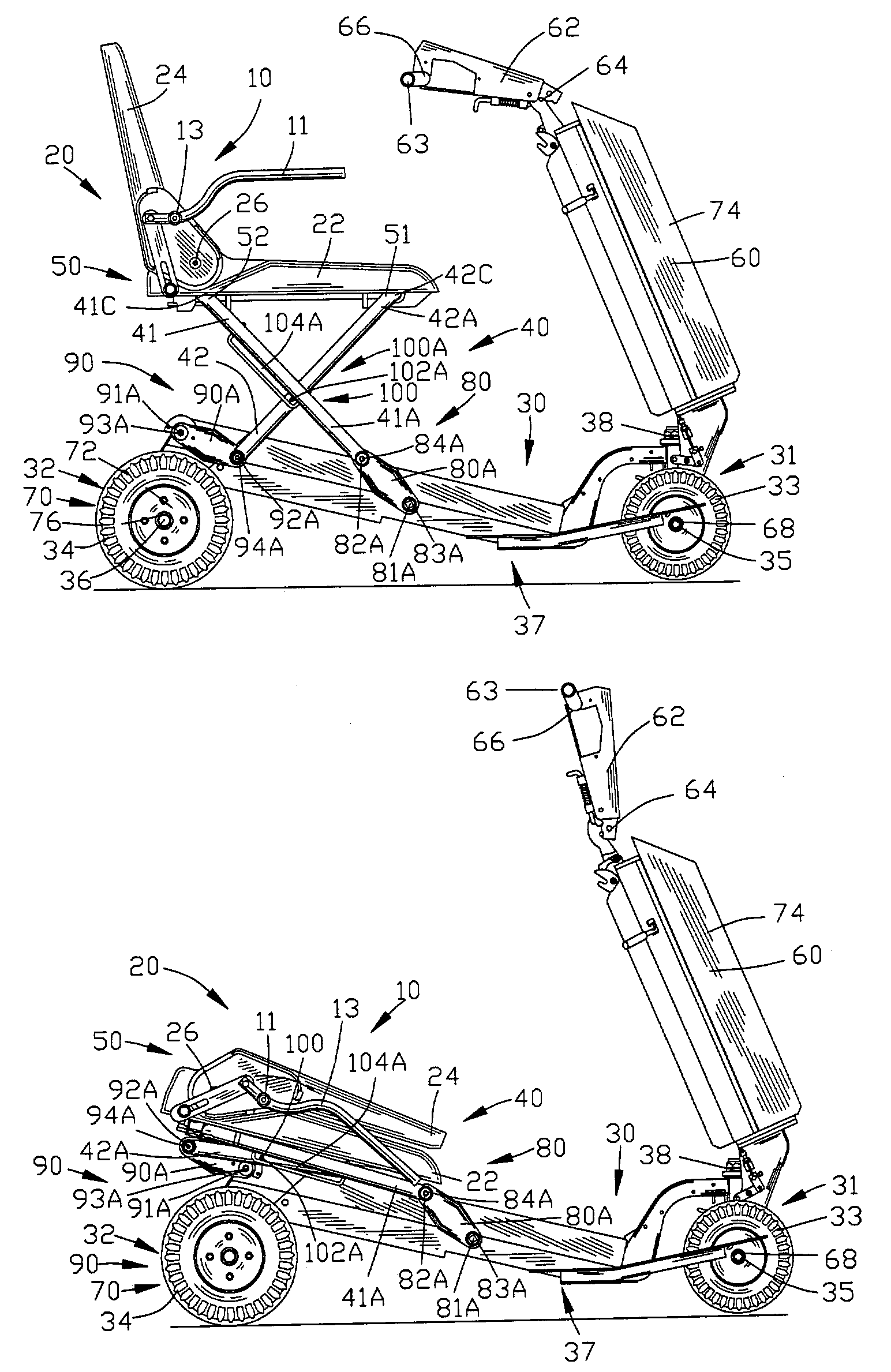
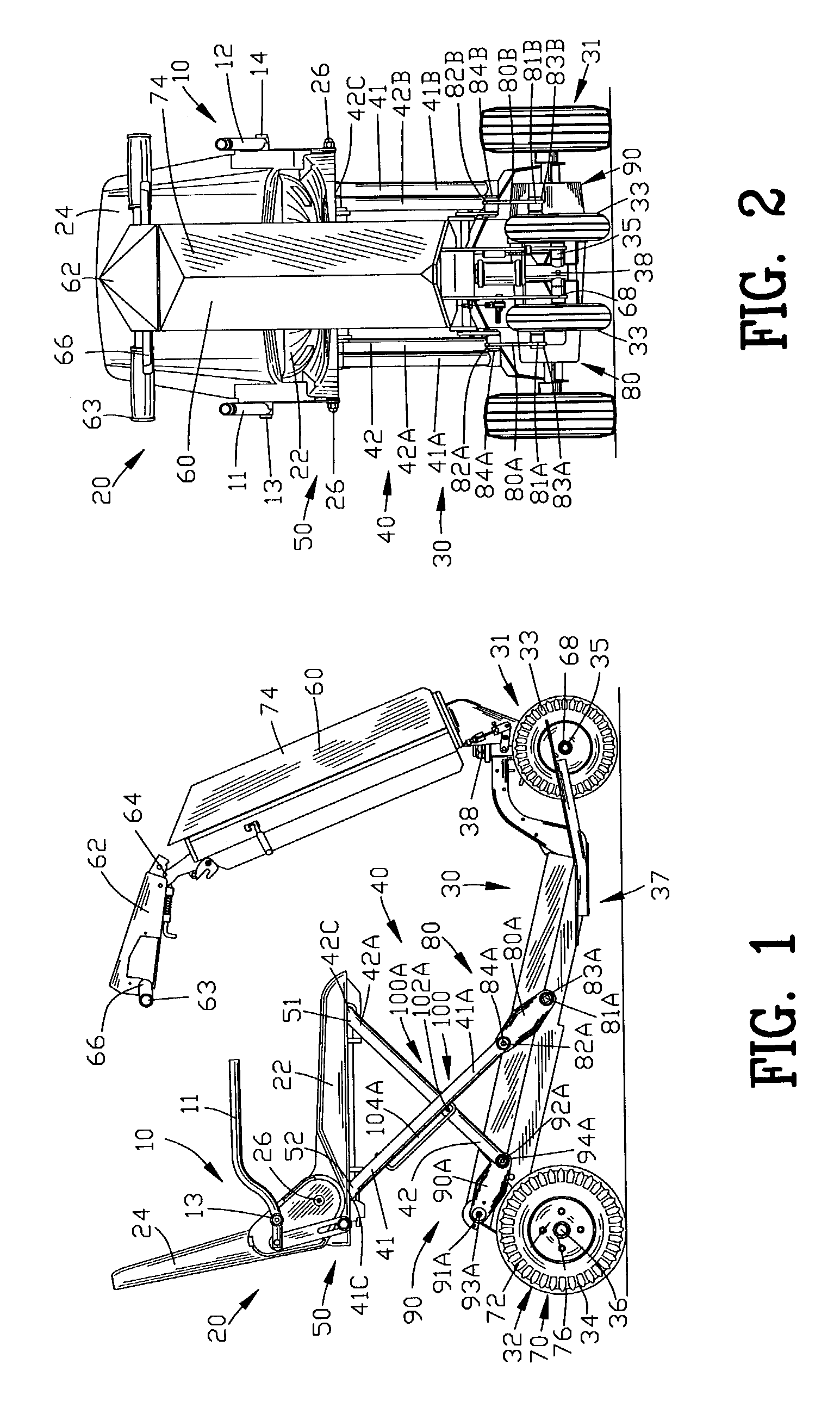
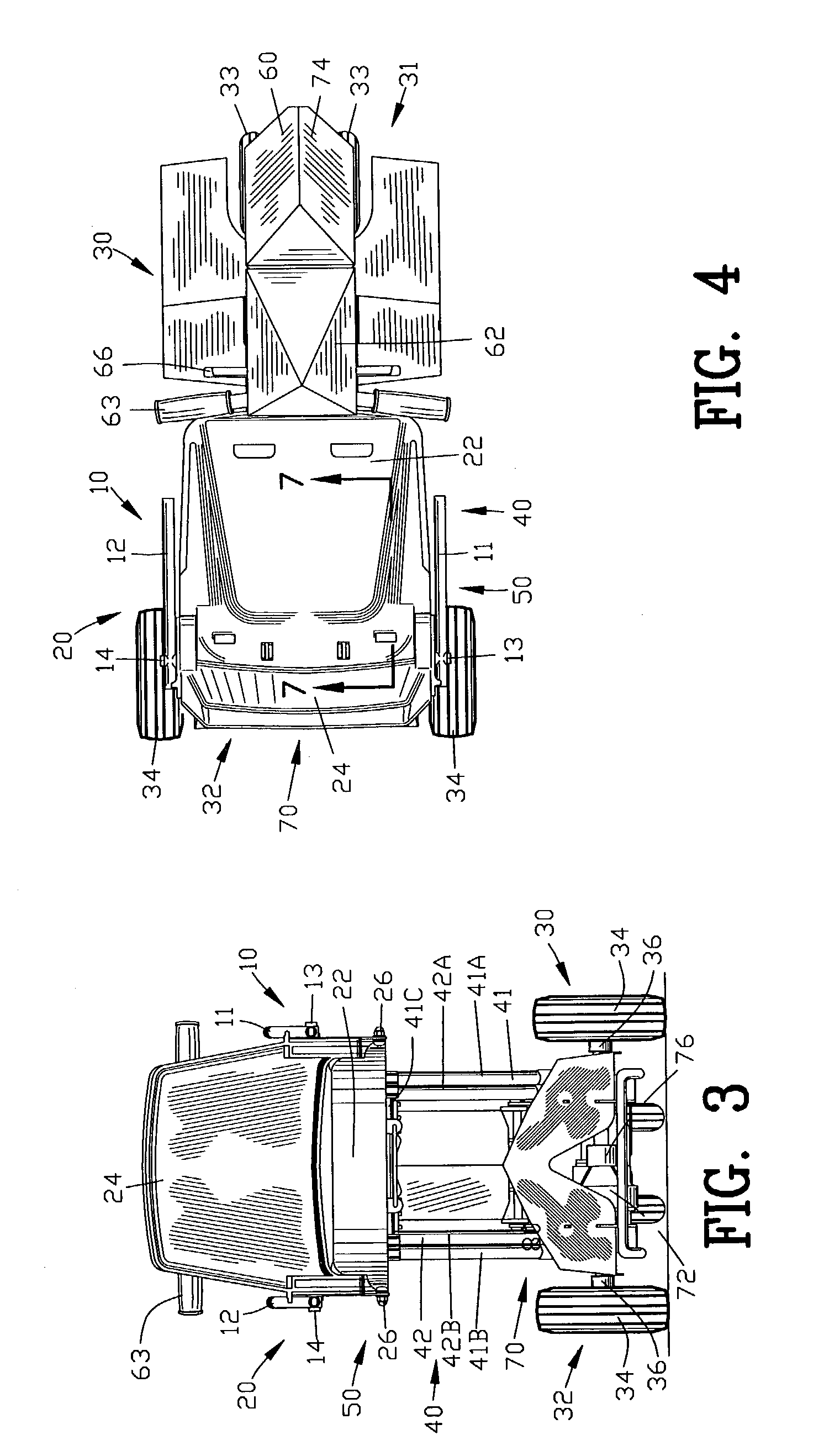
[0072]FIGS. 1–4 illustrate various views of a retractable armrest 10 for a foldable chair 20 incorporating the present invention. In this example, the foldable chair 20 is shown attached to a personal mobility vehicle 30 for transporting an operator. Although the retractable armrest 10 for the foldable chair 20 is shown associated with a personal mobility vehicle 30, it should be appreciated by those skilled in the art that the retractable armrest 10 for the foldable chair 20 may be applied to other suitable applications disassociated with a personal mobility vehicle 30.

[0073]The personal mobility vehicle 30 may be a manual personal mobility vehicle or an electrically powered personal mobility vehicle such as power wheel chair, a scooter or any other suitable vehicle. In this example, the personal mobility vehicle 30 is shown as a foldable personal mobility vehicle 30 but it should be appreciated by those skilled in the art that the personal mobility vehicle 30 may be a conventional...


PUM


Abstract

A retractable armrest is disclosed for a foldable chair. The chair has a seat and a backrest with the backrest being pivotably mounted to the seat by a chair pivot for movement between an operating position and a folded position. A link pivotably operates between armrest and the seat for enabling the armrest to be rotated into the retracted position when the backrest is in the operating position. The link rotates the armrest from the extended position to the retracted position upon the backrest being moved from the operating position to the folded position. The foldable chair is suitable for use on a personal mobility vehicle such as a scooter, a power wheel chair, a foldable personal mobility vehicle or any other suitable chair.

Description

BACKGROUND OF THE INVENTION[0001]1. Field of the Invention[0002]This invention relates to seating and more particularly to a retractable armrest for a foldable chair such as a foldable chair of a personal mobility vehicle.[0003]2. Description of the Related Art[0004]The popularity of personal mobility vehicles has dramatically increased over the last several decades. This increase in the popularity of personal mobility vehicles is due to many factors including the advent of new structural techniques and materials.[0005]Although personal mobility vehicles, have provide the desired mobility, the personal mobility vehicles of the prior art suffered from certain disadvantages. Firstly, the personal mobility vehicles of the prior art were difficult to store during nonuse of the personal mobility vehicles. In general, the size of the personal mobility vehicles of the prior art prohibited the storage of the personal mobility vehicles within a closet or a small room. Secondly, the personal ...

Claims


Application Information

Patent Timeline
Patent Type & Authority Patents(United States)
IPC IPC(8): A47C7/54B60N2/30B60N2/38B60N2/46B60N2/75
CPCB60N2/3011B60N2/3065B60N2/309B60N2/4606A61G2005/125A61G5/125B60N2/753
Inventor JAREMA, III, STEPHENDWYER, JR., EDWARD J.
Owner ELECTRIC MOBILITY
Learn More