Suspension for personal mobility vehicle

a technology for suspension systems and mobility vehicles, applied in the direction of wheelchairs/patient conveyances, foldable cycles, cycles, etc., can solve problems such as inability to function well on irregular or uneven services

Inactive Publication Date: 2004-01-06
ELECTRIC MOBILITY
View PDF17 Cites 20 Cited by
  • Summary
  • Abstract
  • Description
  • Claims
  • Application Information

AI Technical Summary

Benefits of technology

Another object of this invention is to provide an improved suspension system for a personal mobility vehicle that is suitable for use on regular or even surfaces as well as irregular or uneven surfaces.
Another object of this invention is to provide an improved suspension system for a personal mobility vehicle that is readily adaptable for use with personal mobility vehicles having a take-apart frame.

Problems solved by technology

Unfortunately, the suspension systems of personal mobility vehicles of the prior art were adapted for use on regular or even surfaces and accordingly did not function well on irregular or uneven services.

Method used


Image

  • Suspension for personal mobility vehicle
  • Suspension for personal mobility vehicle
  • Suspension for personal mobility vehicle

Examples


first embodiment

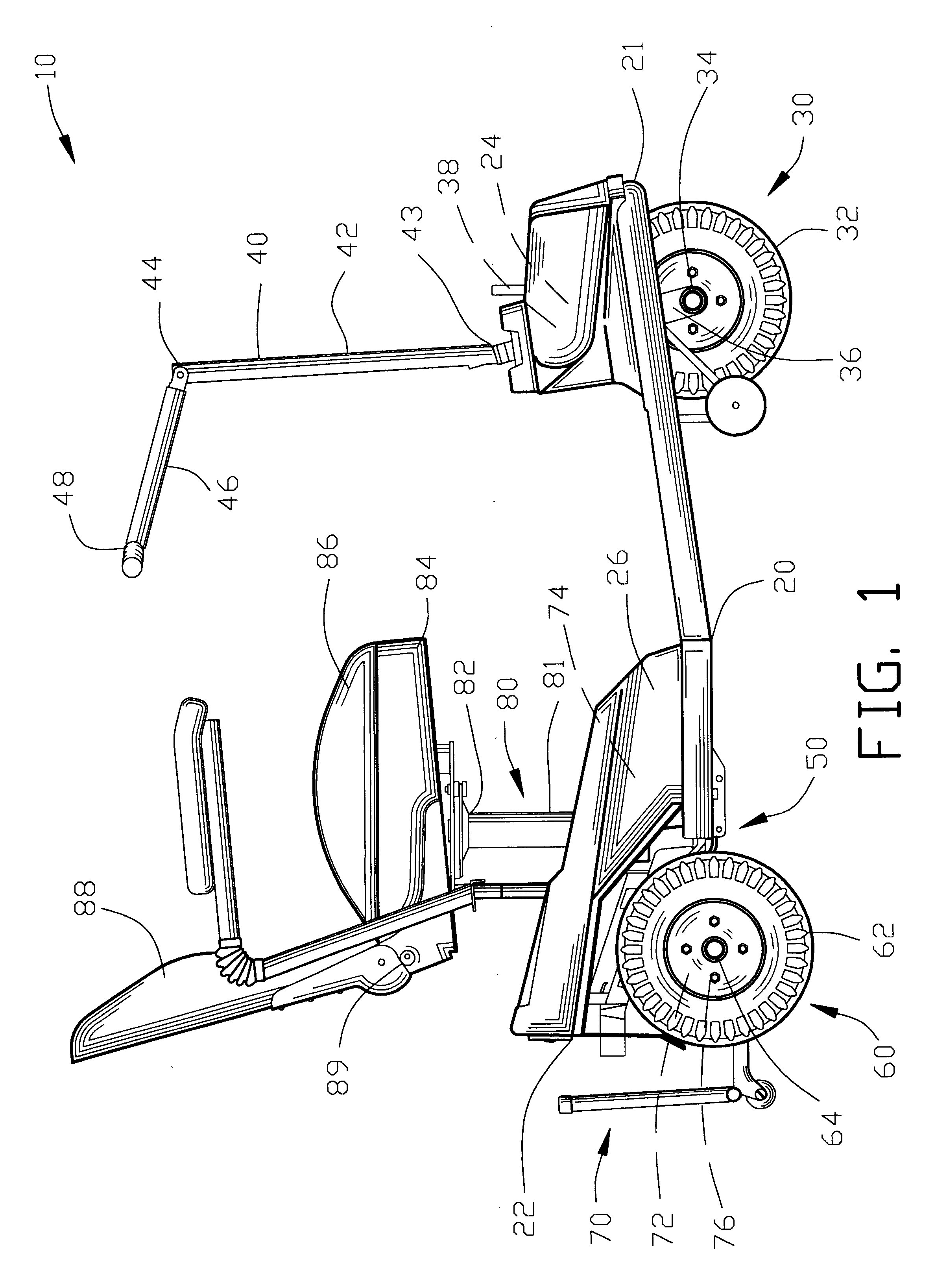
FIG. 4 is an enlarged side view of a portion of FIG. 1 illustrating a portion of a personal mobility vehicle 210 incorporating a suspension system 250 of the present invention. The personal mobility vehicle 210 is shown located on a minor irregular or minor uneven surface 14C having a minor bump 16C.

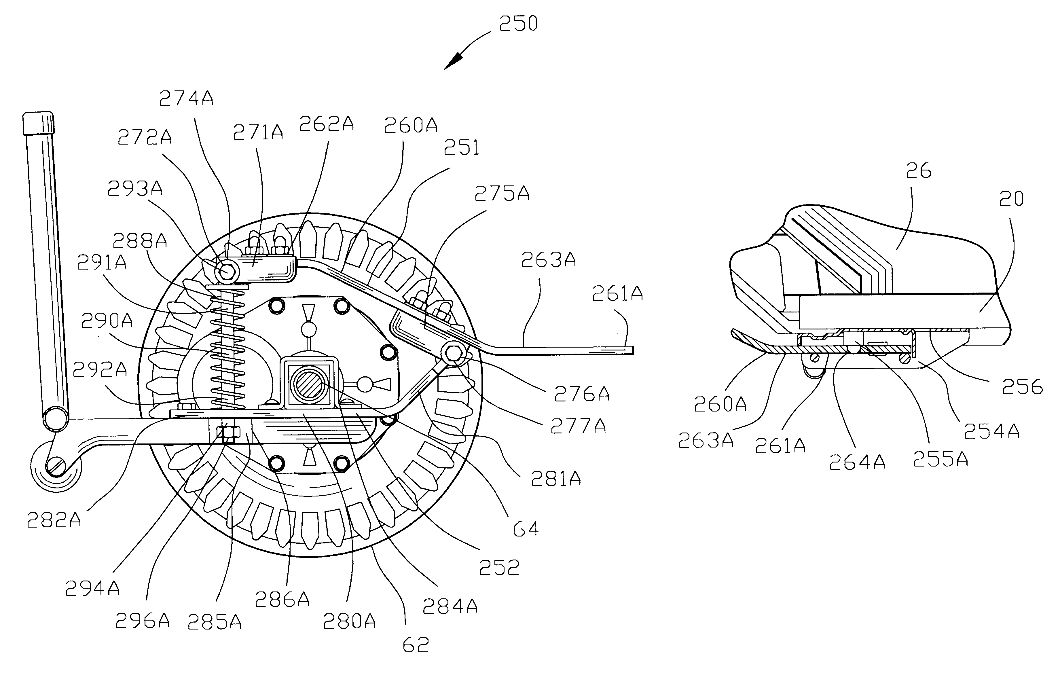
FIG. 5 is a view similar to FIG. 4 illustrating the personal mobility vehicle 210 located on a major irregular or major uneven surface 14D. The major irregular or major uneven surface 14D includes a major bump 16D. The first embodiment of a suspension system 250 of the present invention comprises a dual action suspension system 250.

The suspension system 250 comprises a leaf spring suspension assembly 251 in combination with a coil spring suspension assembly 252. The leaf spring suspension assembly 251 is established to have a stronger resilience then the coil spring suspension assembly 252.

The leaf spring suspension assembly 251 and the coil spring suspension assembly 252 are established...

second embodiment

FIG. 10 is an enlarged side view of a portion of FIG. 1 illustrating a portion of a personal mobility vehicle 310 incorporating a suspension system 350 of the present invention. The personal mobility vehicle 310 is shown located on an even surface 12E.

FIG. 11 is a view similar to FIG. 10 illustrating the personal mobility vehicle 310 located on a major irregular or major uneven surface 14E. The major irregular or major uneven surface 14F includes a major bump 16F. The second embodiment of a suspension system 350 of the present invention comprises a single action suspension system 350.

The suspension system 350 comprises a coil spring suspension assembly 352. The coil spring suspension assembly 352 is designed to be interchangeable with the suspension system 250 shown in FIGS. 4-9. The ability to interchange the suspension system 350 with the suspension system 250 shown in FIGS. 4-9 enables the personal mobility vehicle 10 to be customized to the specific needs of the operator (not sh...


PUM


Abstract

An improved suspension system is disclosed for a personal mobility vehicle comprising an arm assembly pivotably mounted to a fame section. A wheel assembly is connected to the arm assembly. A spring is interposed between the arm assembly and the second frame section for resiliently suspending the wheel assembly relative to the frame section. In one example of the invention, the frame section comprises a rigid frame section of the personal mobility vehicle. In another example of the invention, the frame section comprises a resilient leaf spring resiliently suspending the assembly of the personal mobility vehicle. In another example of the invention, a resilient coil spring interposed between the arm assembly the resilient leaf spring for providing a multiple resilient suspension for the wheel assembly.

Description

1. Field of the InventionThis invention relates to personal mobility vehicles and more particularly to an improved suspension system for providing a resiliently mounted wheel assembly.2. Background of the InventionThe aging population has provided a substantial increase in the use of personal mobility vehicles. Personal mobility vehicles provide persons with partial or total walking disabilities with an increased range and greater flexibility in locomotion. The increased use of personal mobility vehicles has required the development of more technically superior features that enable the personal mobility vehicle to be used in various locations and terrains.Personal mobility vehicles have a pair of powered rear wheels and a steerable front wheel configured in the general appearance of a miniature golf cart. The track of the rear wheels of the adz personal mobility vehicle is generally narrower than a wheelchair. The personal mobility vehicle is usually designed for a tight turning rad...

Claims


Application Information

Patent Timeline
Patent Type & Authority Patents(United States)
IPC IPC(8): B60G11/02B60G11/00B60G9/00B60G11/16B60G11/04A61G5/10A61G5/00
CPCB60G9/003B60G11/04B60G11/16A61G2005/1078B60G2200/31B60G2200/422B60G2202/112B60G2202/12B60G2204/121B60G2204/124B60G2300/24B60G2300/50A61G5/1078
Inventor DWYER, JR., EDWARD JOSEPHJAREMA, STEPHEN JOHN
Owner ELECTRIC MOBILITY
Why Eureka
Try Eureka