RFID antenna

Inactive Publication Date: 2006-09-21
TRANSPACIFIC TECH
7 Cites 256 Cited by

AI-Extracted Technical Summary

Problems solved by technology

The lack of a built-in energy source, however, also limits the effective operating range of a passive RFID tag with respect to the given energy in an interrogation signal.
Unfortunately, simply increasing the power level of an interrogation signal to insure successful interrogator-tag communications is not always possible.
For instance, simple inefficiency can exacerbate problems such as battery life and heat dissipation in the interrogator.
Of more serious concern, RF energy radiation intended for one system can interfere with other electronic systems and, in extreme cases, can be unsafe for biological systems, e.g., humans, animals, plants, etc.
Unfortunately, these a...

Benefits of technology

[0018] An advantage of the present invention is that it is particularly suitable for use in passive-type RFID tags by virtue of its high efficiency. Although, the present invention is also quite suitable and beneficial for use in many active-type RFID tag designs.
[0019] Another advantage of the invention is that it can be implemented as a simple structure having a small size, thus making it suitable to serve in applications where a size is a limitation and making its manufacture and materials requirements quite economical.
[0020] Another advantage of the invention is that it permits a more omni directional ant...

Abstract

An antenna particularly suitable for use in radio frequency identification (RFID) transponders. First and second half portions each include nominally straight conductive sections primarily defining a radiating characteristic and nominally spiral conductive sections creating a positive reactive characteristic of the antenna. The straight conductive sections have feed points for connecting the antenna into the RFID transponder, and further connect with the respective spiral conductive sections. The first and said second half portions characterize the antenna as being a dipole type, and adding an optional loop section connecting the straight conductive sections can further characterize it as being of a folded dipole type.

Application Domain

Technology Topic

Image

  • RFID antenna
  • RFID antenna
  • RFID antenna

Examples

  • Experimental program(1)

Example

[0029] In the various figures of the drawings, like references are used to denote like or similar elements or steps.
BEST MODE FOR CARRYING OUT THE INVENTION
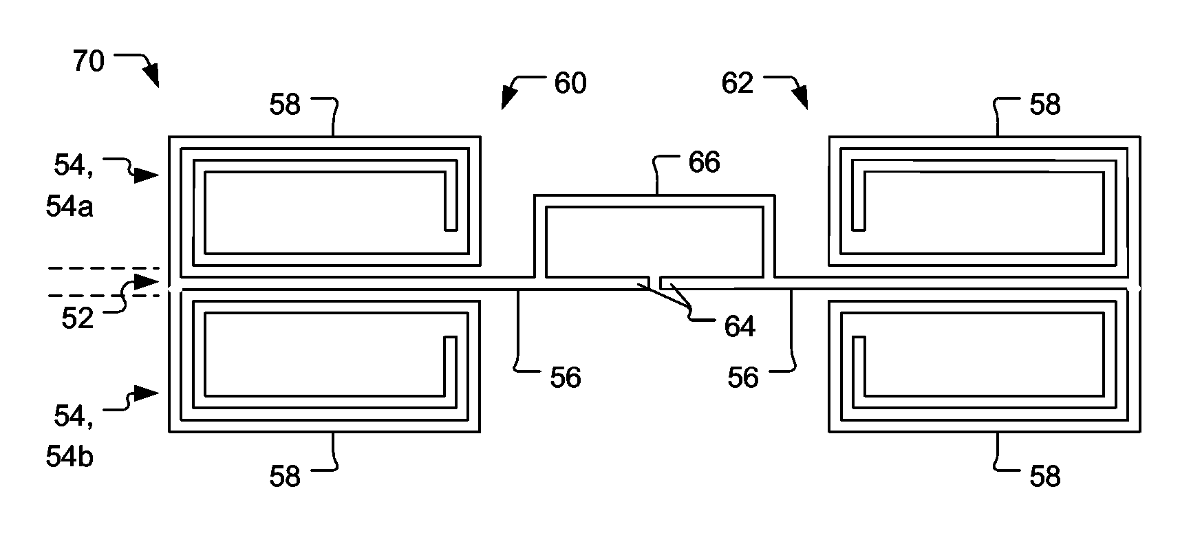
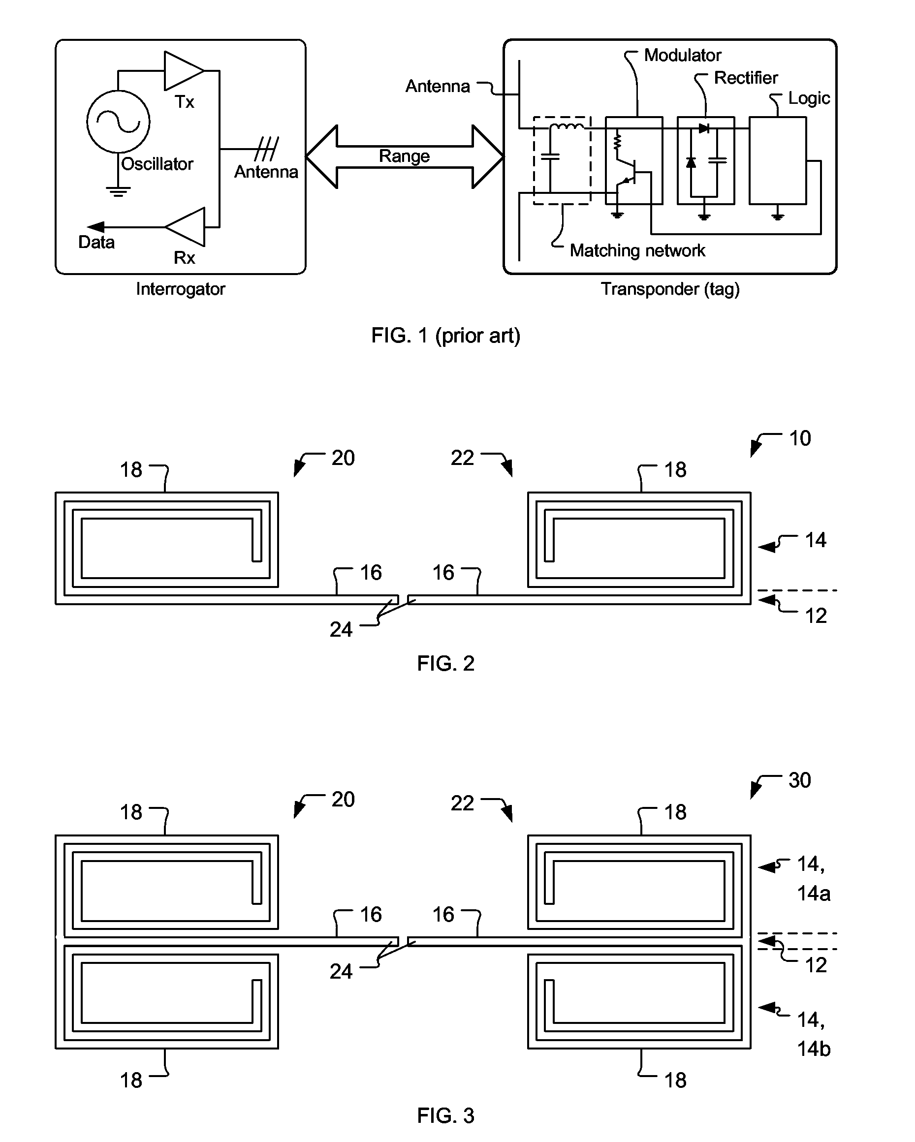
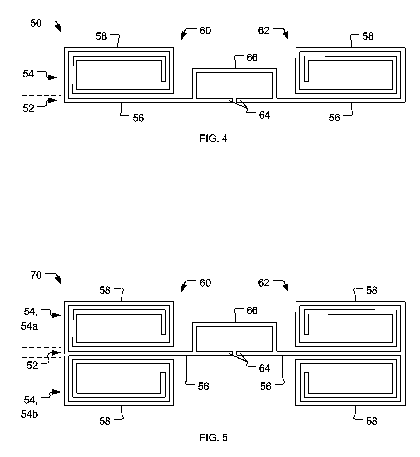
[0030] A preferred embodiment of the present invention is an antenna for use in Radio Frequency Identification (RFID) transponders. As illustrated in the various drawings herein, and particularly in the views of FIG. 2-5, preferred embodiments of the invention are depicted by the general reference characters 10, 30, 50, and 70.
[0031]FIG. 2 depicts an antenna 10 in accord with the present invention that consists of two sections 12, 14. The first section 12 consists of the mainly radiating components, here straight conductive traces 16, while the second section 14 consists of substantially reactive components, here spiral conductive traces 18. The spirals shown in the figures herein are typical, and might have an arbitrary number of turns, lengths, widths, etc.
[0032] In the characteristic manner of dipole-type antennas, the antenna 10 here has a left dipole half 20 mirrored by a right dipole half 22. These half's of the antenna 10 do not correspond with and should not be confused with the sections 12, 14. The left dipole half 20 of the antenna 10 includes both a first section 12 and a second section 14, as does the right dipole half 22. Each first section 12 includes a feed point 24, for connecting the antenna 10 to a transponder chip (not shown). As shown, each first section 12 also, directly or indirectly, connects to its respective second section 14.
[0033] In use, the spiral structures of the second sections 14 (the spiral conductive traces 18 in FIG. 2) substantially increase the imaginary part of the impedance of the antenna 10. The use of such a spiral structure has the particular advantage over traditional meander-line structures as it creates the positive reactive component of the impedance in a more compact size.
[0034]FIG. 3 depicts another antenna 30, extending the dipole type principles of the antenna 10 in FIG. 2. The antenna 30 also consists of two sections 12, 14, but the second section 14 here has two parts, a sub-section 14a and a sub-section 14b, that include four spiral conductive traces 18.
[0035]FIG. 4 depicts an antenna 50 in accord with the present invention that also consists of two sections 52, 54. The first section 52 consists of the mainly radiating components (straight conductive traces 56) and the second section 54 consists of the substantially reactive components (spiral conductive traces 58). The antenna 50 here also has a left folded dipole half 60 and a mirrored right folded dipole half 62, with each first section 52 including a feed point 64 for connection to a transponder chip and with each first section 52 also, directly or indirectly, connecting to its respective second section 54. Unlike the dipole antenna 10 of FIG. 2, however, the antenna 50 of FIG. 3 has a loop section 66 connecting the dipole half's 60, 62 in the manner that conductive loops are traditionally used to create folded dipole-type antennas.
[0036] In use, here as well, the spiral structures of the second sections 54 (the spiral conductive traces 58 in FIG. 3) substantially increase the imaginary part of the impedance of the antenna 50 and distinguish it over traditional structures, such as meander-line based designs.
[0037]FIG. 5 depicts another antenna 70, extending the folded-dipole type principles of the antenna 50 in FIG. 4. The antenna 70 also consists of two sections 52, 54, but the second section 54 here has two parts, a sub-section 54a and a sub-section 54b, that include four spiral conductive traces 58.
[0038] The benefits provided by the present invention are substantial. For example, in a standard (straight) dipole antenna having an imaginary part of 63 Ohms for an input impedance at 915 MHz, the length should be more than 160 mm. However, using the embodiment in FIG. 2 (antenna 10), it is possible to achieve the same value with a length of only 50 mm and a width of only 8 mm, which is a considerable improvement over the standard dipole.
[0039] In summary, the present invention relates to radio frequency identification (RFID) systems and more particularly to antennas for use in an RFID devices wherein the impedance more optimally matches with the relevant radio frequency (RF) circuitry in the transponder chip. Two major sections form the antenna, with one of them consisting of the mainly radiating components, e.g. conductive metal traces, and the other being substantially reactive components, e.g. consisting of spiral metal traces. The sections are, directly or indirectly, connected, with the mainly radiating components having suitable feed points for connection to the transponder chip. Optionally, loop antenna characteristics can be added by providing a loop section, in largely conventional manner, to the folded dipole structure of the inventive antenna that has now been described.
[0040] While various embodiments have been described above, it should be understood that they have been presented by way of example only, and not limitation. Thus, the breadth and scope of the invention should not be limited by any of the above described exemplary embodiments, but should be defined only in accordance with the following claims and their equivalents.

PUM

no PUM

Description & Claims & Application Information

We can also present the details of the Description, Claims and Application information to help users get a comprehensive understanding of the technical details of the patent, such as background art, summary of invention, brief description of drawings, description of embodiments, and other original content. On the other hand, users can also determine the specific scope of protection of the technology through the list of claims; as well as understand the changes in the life cycle of the technology with the presentation of the patent timeline. Login to view more.

Similar technology patents

Classification and recommendation of technical efficacy words

  • High efficiency
  • Small size

Rectenna

Owner:IHI AEROSPACE CO LTD
Why Eureka
Try Eureka