Polyaxial bone anchor with helical capture connection, insert and dual locking assembly

a technology helical capture, which is applied in the field of polyaxial bone screws, can solve the problems of increasing the stress on the various polyaxial bone screw components, unable to tightly engage the connection top, and unable to prevent unintentional disassembly, and achieves convenient, secure and fastening to each other and to bone. , the effect of preventing unintentional disassembly

Inactive Publication Date: 2009-03-05
JACKSON
View PDF99 Cites 227 Cited by
  • Summary
  • Abstract
  • Description
  • Claims
  • Application Information

AI Technical Summary

Benefits of technology

[0009]Objects of the invention include one or more of the following: providing a polyaxial bone screw having a shank with an integral upper end portion that threadably mates with a retaining structure configured for polyaxial motion with respect to the receiver prior to locking; providing such a polyaxial bone screw that includes a pressure insert that exerts pressure exclusively on an upper surface of the integral and stronger shank upper end portion, the upper surface being substantially spaced from the retaining structure; providing such an implant wherein all of the parts remain together and do not separate; providing a lightweight, low profile polyaxial bone screw that assembles in such a manner that the components cooperate to create an overall structure that prevents unintentional disassembly; providing a polyaxial bone screw that provides independent locking for the bone screw shank and the longitudinal connecting member; providing such an assembly that includes a longitudinal connecting member that may be of non-circular or circular cross-section; providing such an assembly that remains in a locked position even if the longitudinal connecting member undergoes deformation such as creep; providing a polyaxial bone screw with features that provide adequate frictional or gripping surfaces for bone implantation tools and may be readily, securely fastened to each other and to bone; and providing apparatus and methods that are easy to use and especially adapted for the intended use thereof and wherein the apparatus are comparatively inexpensive to make and suitable for use.
[0010]Other objects and advantages of this invention will become apparent from the following description taken in conjunction with the accompanying drawings wherein are set forth, by way of illustration and example, certain embodiments of this invention.
[0011]The drawings constitute a part of this specification and include exemplary embodiments of the present invention and illustrate various objects and features thereof.

Problems solved by technology

This is sometimes very difficult or impossible to do.
When a rod or other longitudinal connecting member exhibits creep deformation over time, the closure top may no longer tightly engage the connecting member.
However, such loosening also results in loosening of the frictional engagement between the receiver and the bone screw shank that locks the angular orientation of the shank with respect to the receiver.
Body movement and stresses may then result in undesirable pivoting of the shank with respect to the receiver causing mis-alignment, greater stress and further loosening of the various polyaxial bone screw components.
However, one of the drawbacks to such a polyaxial implant is that to maintain a relatively non-bulky, low profile assembly, the numerous inserts and other component parts of such an assembly have thin walls that provide the desired low profile but otherwise lack sufficient strength to withstand the stresses placed thereon by the human body and other component parts of the bone screw assembly.
However, such a nut adds undesirable bulk to the assembly and may lead to undesirable interference with vertebrae and other medical implants.

Method used


Image

  • Polyaxial bone anchor with helical capture connection, insert and dual locking assembly
  • Polyaxial bone anchor with helical capture connection, insert and dual locking assembly
  • Polyaxial bone anchor with helical capture connection, insert and dual locking assembly

Examples


Embodiment Construction

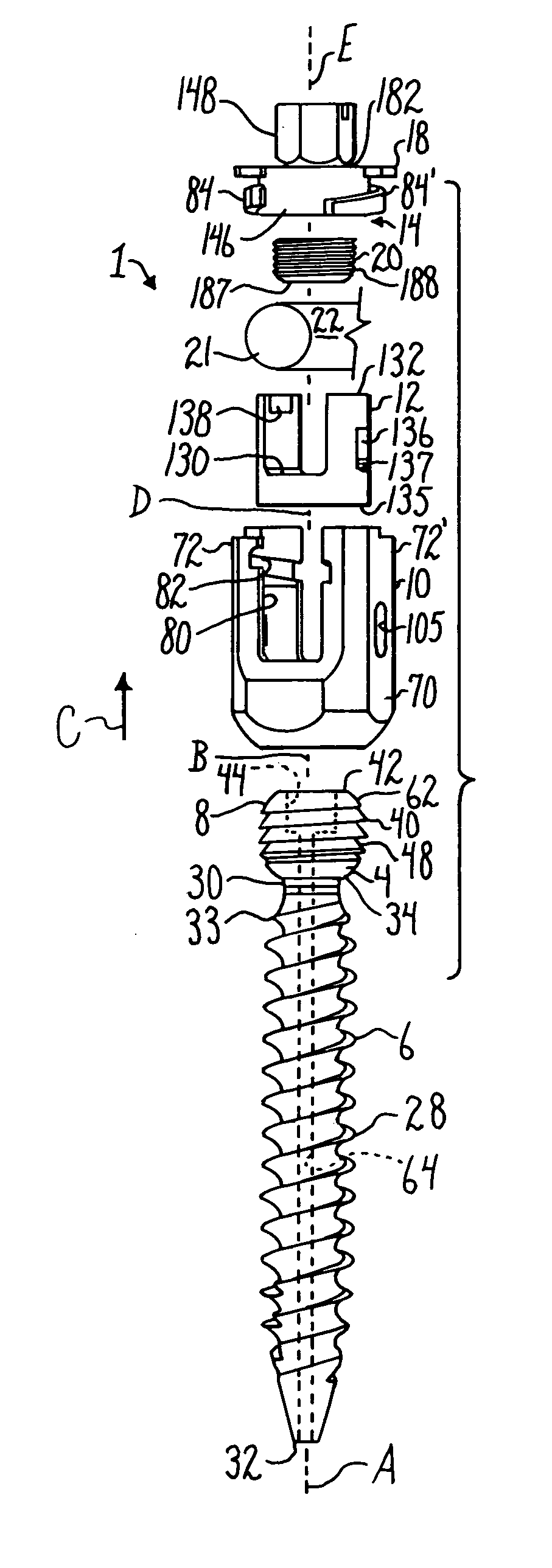
[0052]As required, detailed embodiments of the present invention are disclosed herein; however, it is to be understood that the disclosed embodiments are merely exemplary of the invention, which may be embodied in various forms. Therefore, specific structural and functional details disclosed herein are not to be interpreted as limiting, but merely as a basis for the claims and as a representative basis for teaching one skilled in the art to variously employ the present invention in virtually any appropriately detailed structure. It is also noted that any reference to the words top, bottom, up and down, and the like, in this application refers to the alignment shown in the various drawings, as well as the normal connotations applied to such devices, and is not intended to restrict positioning of bone attachment assemblies of the application and cooperating connecting members in actual use.

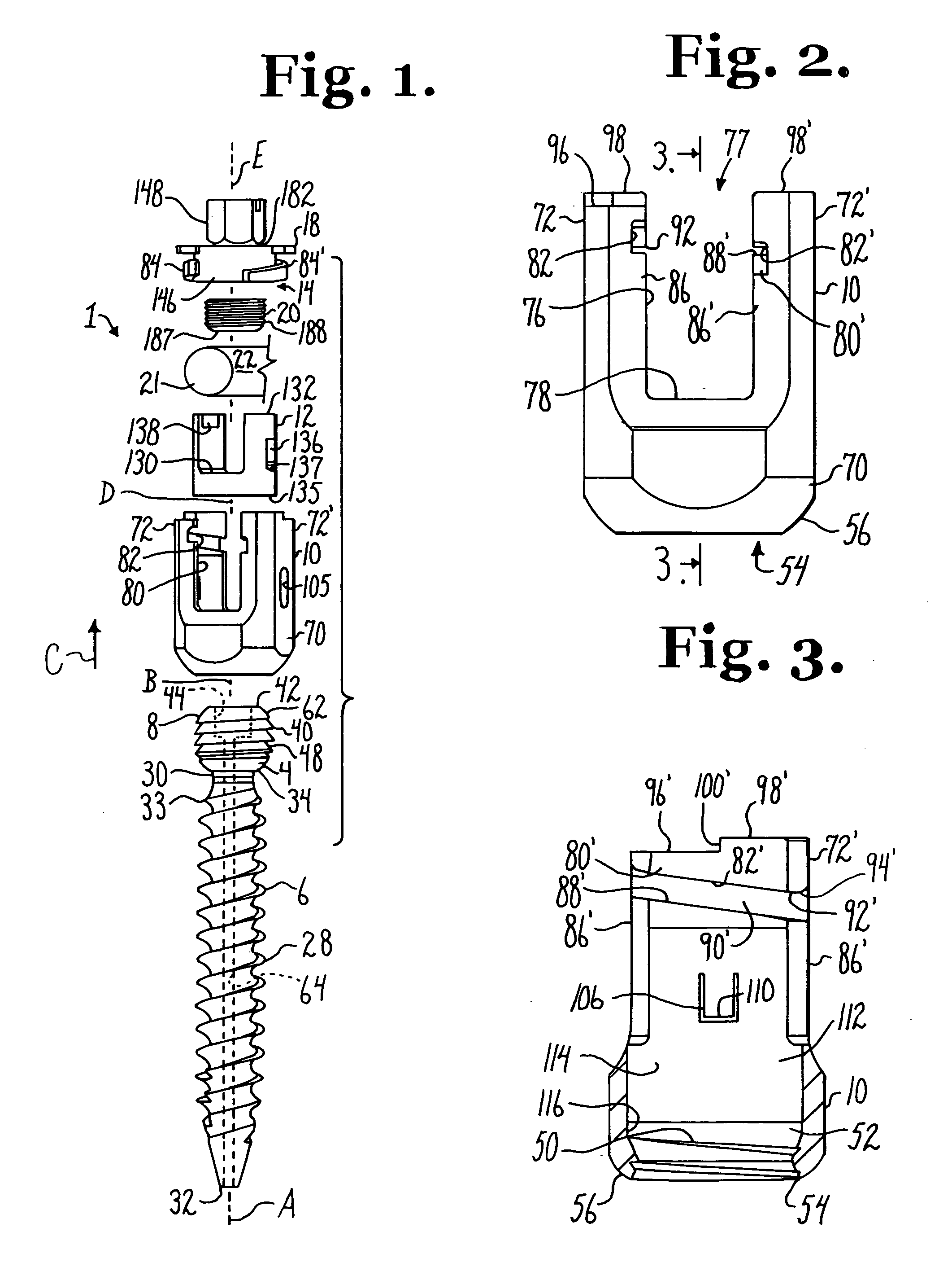
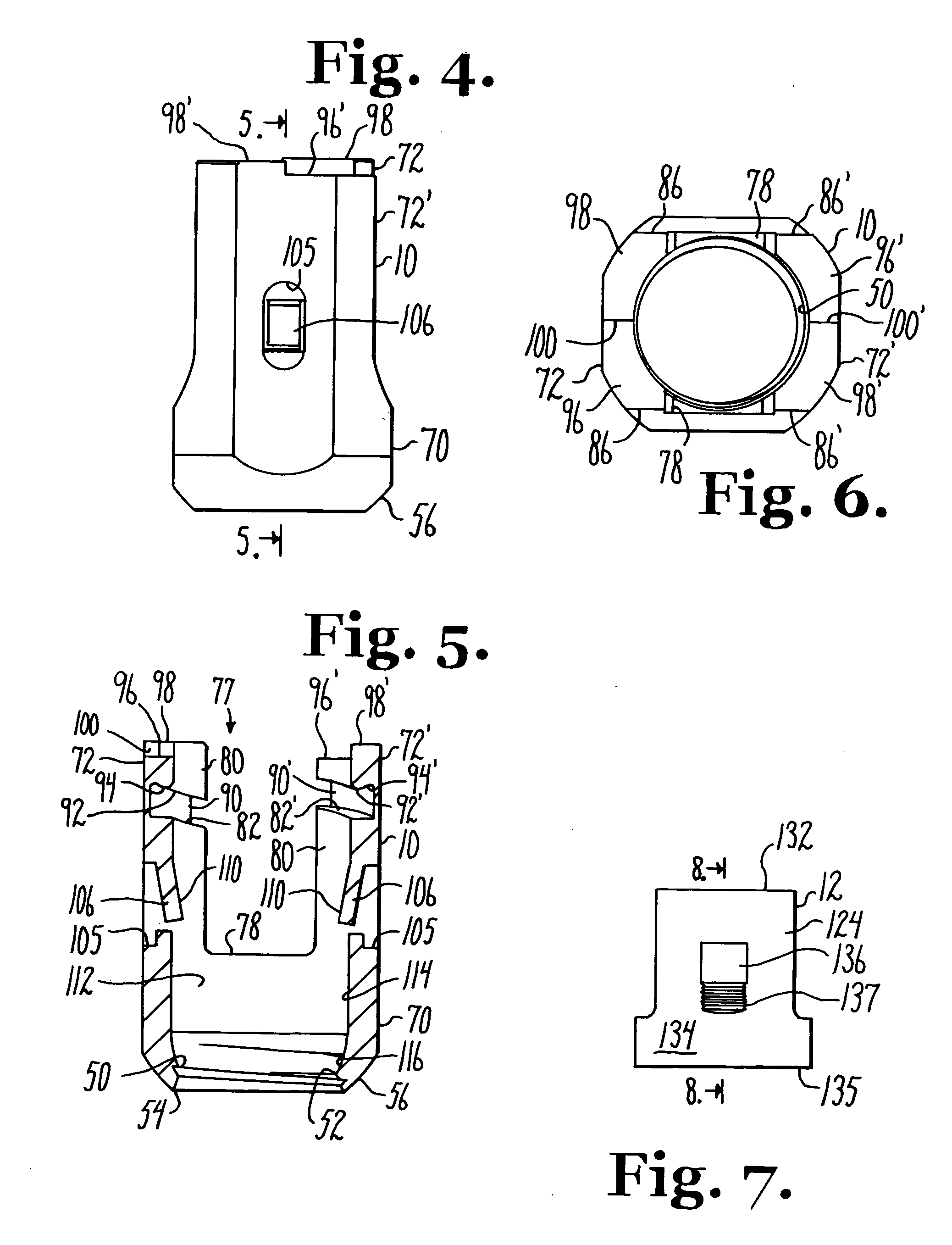
[0053]With reference to FIGS. 1-21, the reference number 1 generally represents an embodiment of...


PUM


Abstract

A medical implant assembly includes a polyaxial bone anchor having a shank, a receiver, a lower compression insert with surfaces for closely receiving an elongate connecting member and a dual closure structure that may include a single flange or helical flange. The dual closure structure independently engages the connecting member and the lower compression insert. A threaded capture connection of the bone anchor includes a shank upper surface exclusively engaging the lower compression insert and a retainer threadably attached to the shank and spaced from the upper surface, the retainer configured for polyaxial motion with respect to the receiver prior to locking.

Description

CROSS-REFERENCE TO RELATED APPLICATIONS[0001]This application claims the benefit of U.S. Provisional Application No. 60 / 000,964 filed Oct. 30, 2007, incorporated by reference herein. This application is also a continuation-in-part of U.S. patent application Ser. No. 11 / 522,503 filed Sep. 14, 2006 that is a continuation-in-part of U.S. patent application Ser. No. 11 / 024,543 filed Dec. 20, 2004, both of which are incorporated by reference herein. This application is also a continuation-in-part of U.S. patent application Ser. No. 11 / 140,343 filed May 27, 2005, incorporated by reference herein. This application is also a continuation-in-part of U.S. patent application Ser. No. 10 / 986,377 filed Nov. 10, 2004, incorporated by reference herein. This application is also a continuation-in-part of U.S. patent application Ser. No. 10 / 818,555 filed Apr. 5, 2004 that is a continuation of U.S. patent application Ser. No. 10 / 464,633 filed Jun. 18, 2003, now U.S. Pat. No. 6,716,214, both of which a...

Claims


Application Information

Patent Timeline
Patent Type & Authority Applications(United States)
IPC IPC(8): A61B17/04
CPCA61B17/7037A61B17/7032A61B17/86A61B2560/0406
Inventor JACKSON, ROGER P.
Owner JACKSON
Why Eureka
Try Eureka