Bun laner

a technology for buns and lanes, applied in packaging, sorting, membrane technology, etc., can solve the problem of uncomplicated vacuum mechanism for blocking full lanes

Inactive Publication Date: 2006-10-31
HENRY GRP INC THE
View PDF17 Cites 33 Cited by
  • Summary
  • Abstract
  • Description
  • Claims
  • Application Information

AI Technical Summary

Benefits of technology

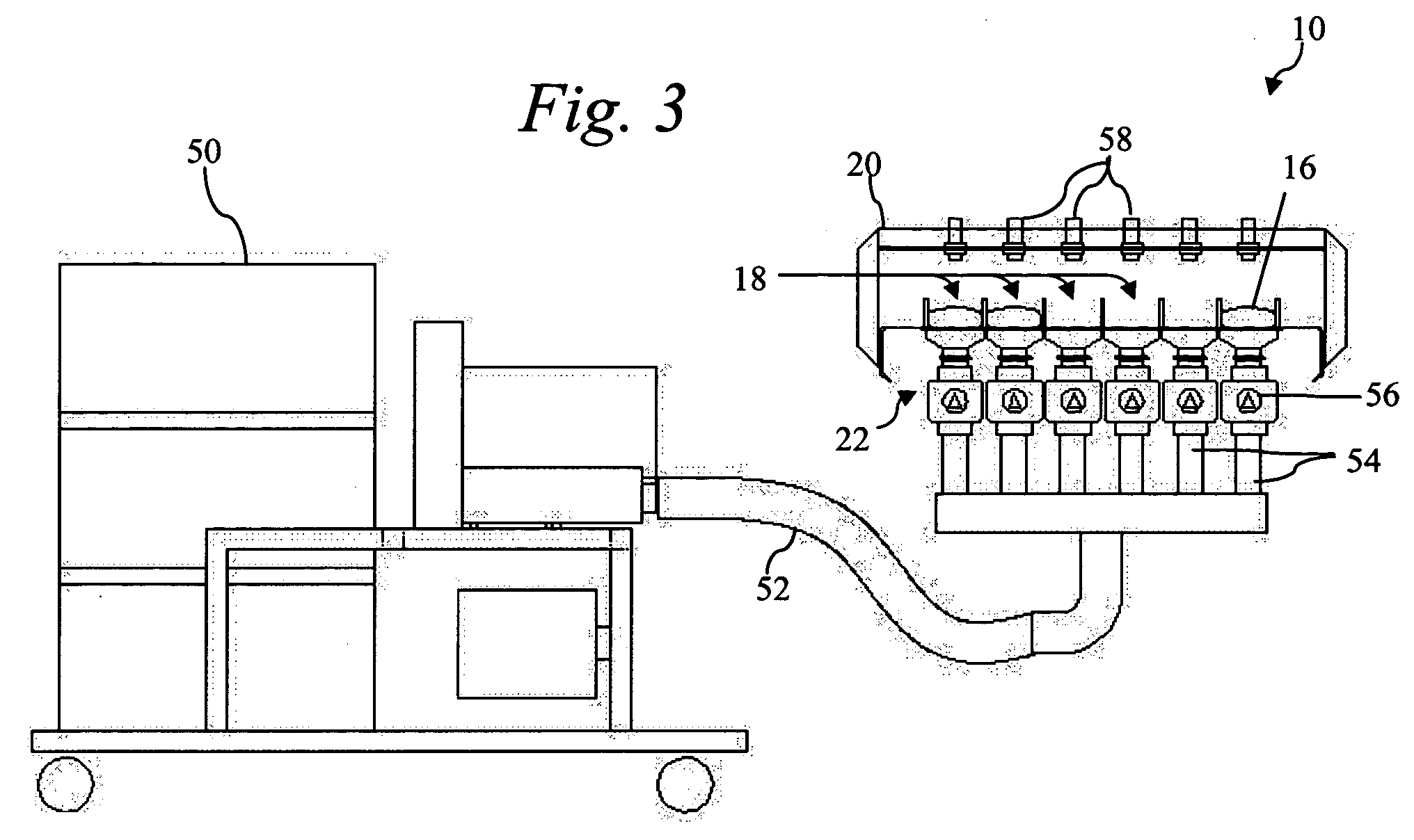
[0011]The present invention provides significant advantages over the prior art. First, full lanes can be blocked using an uncomplicated vacuum mechanism. Second, the lanes are blocked without causing damage to the buns.

Problems solved by technology

First, full lanes can be blocked using an uncomplicated vacuum mechanism.

Method used


Image

  • Bun laner
  • Bun laner
  • Bun laner

Examples


Embodiment Construction

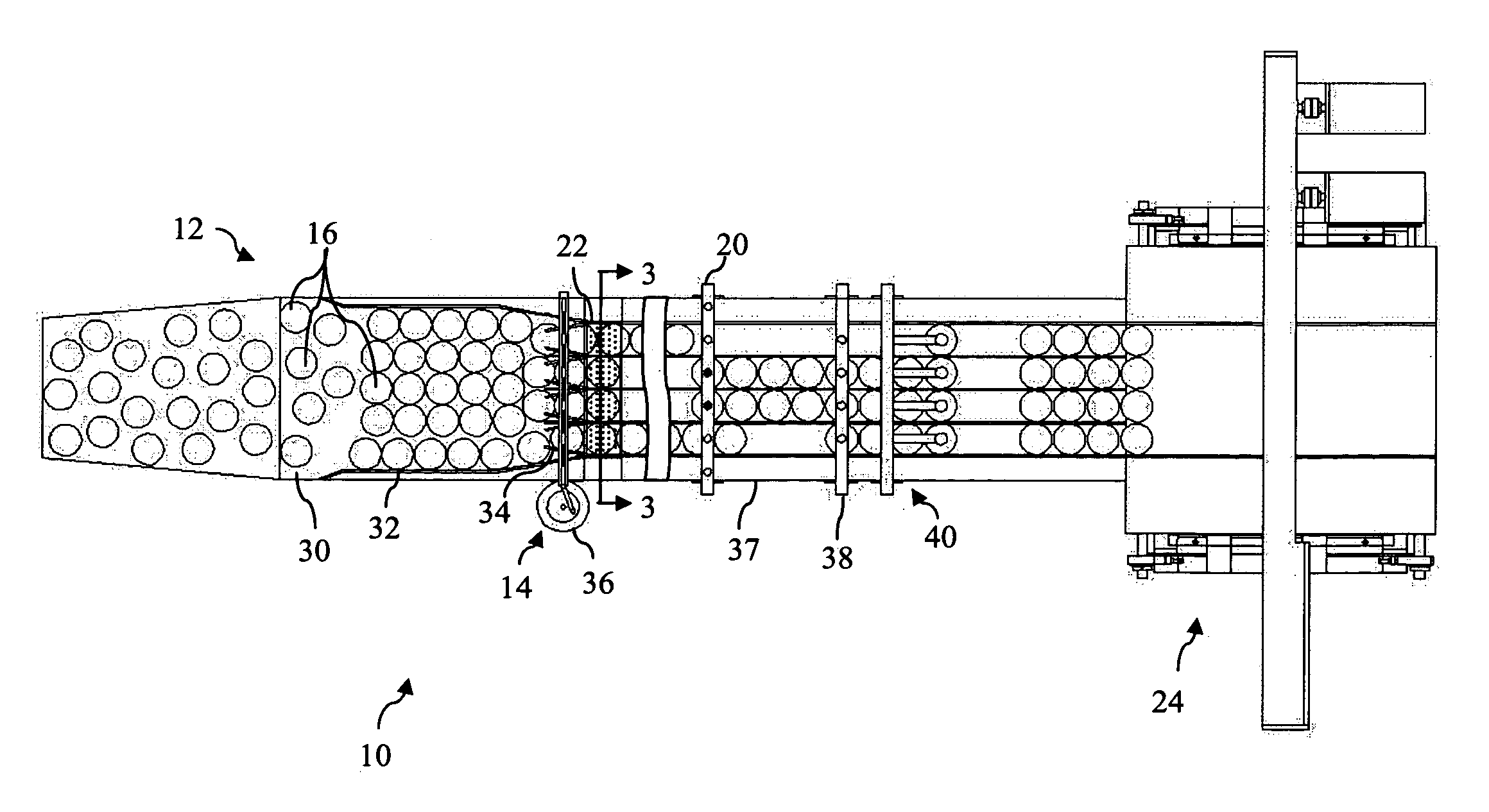
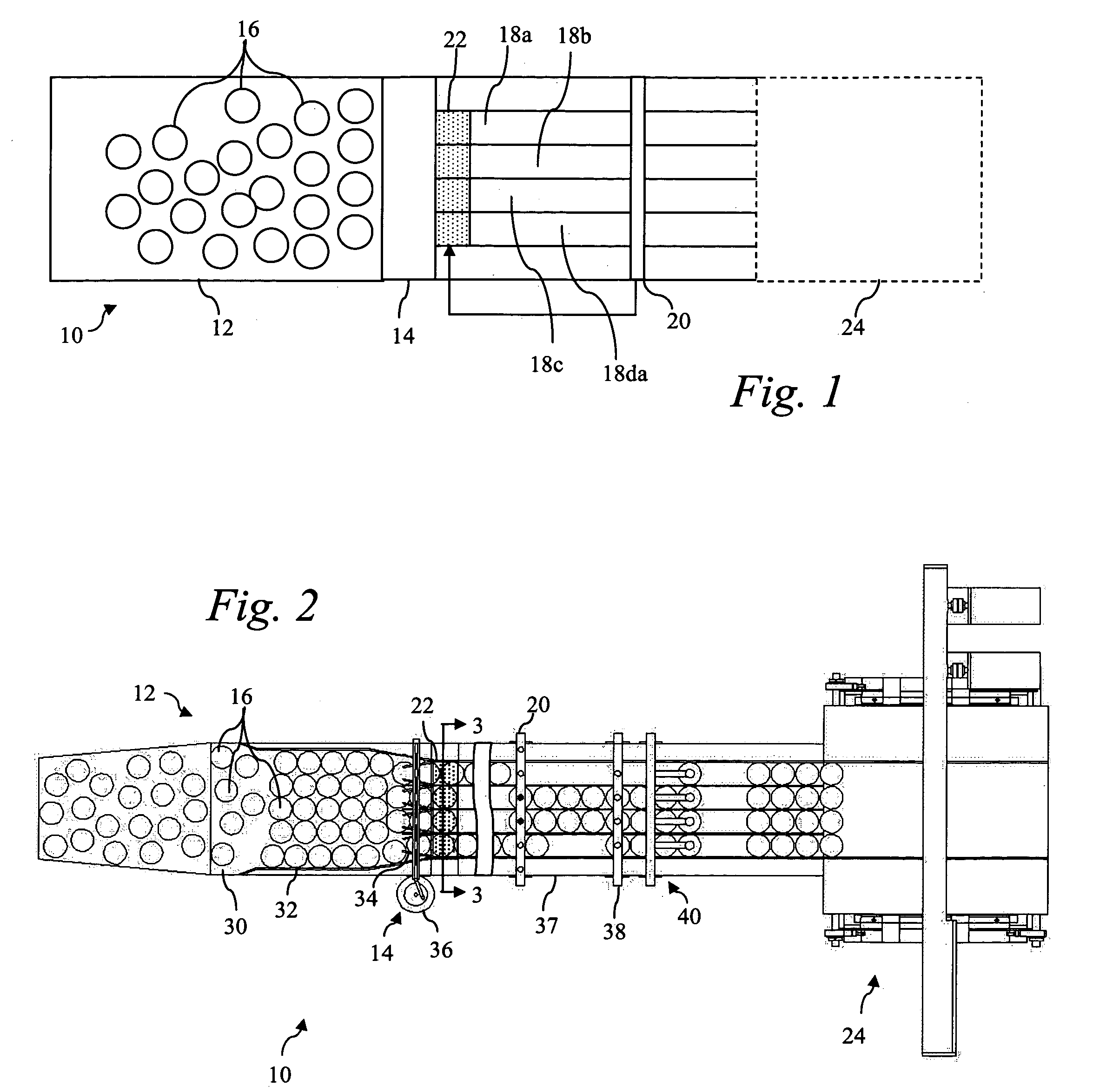
[0017]The present invention is best understood in relation to FIGS. 1–4 of the drawings, like numerals being used for like elements of the various drawings.

[0018]FIG. 1 illustrates a basic diagram of a bun laner 10. Buns enter the laner 10 in staging area 12 after cooling an de-panning. Sorting mechanism 14 aids in directing buns 16 from the staging area 12 into one of the lanes 18. Bun detection unit 20 detects when the number of buns in a lane have reached a predetermined point in the lane. Lane impeder 22 can impede bun movement into one or more selected lanes, responsive to a signal from bun detection unit 20. A packaging device 24 receives buns from the lanes 18a–d and packages the buns 16.

[0019]In operation, the staging area 16 includes a conveyor belt which transports the buns towards the sorting mechanism 14. The sorting mechanism could use, for example, moving guides as shown in FIGS. 2–4. The purpose of the sorting mechanism is to direct randomly placed buns 16 into a lane...


PUM


Abstract

A bun laner sorts buns into a predetermined number of lanes, for providing buns to a packaging unit. The bun laner detects when some lanes are filling faster than other and closes those lanes while the other lanes fill. A vacuum may be used to hold buns in a filled lane in order to close the lane. An optical detection unit may be used to determine when a bun has been stationary at a certain position in the lane for a predetermined amount of time.

Description

CROSS-REFERENCE TO RELATED APPLICATIONS[0001]Not ApplicableSTATEMENT OF FEDERALLY SPONSORED RESEARCH OR DEVELOPMENT[0002]Not ApplicableBACKGROUND OF THE INVENTION[0003]1. Technical Field[0004]This invention relates in general to food packaging equipment and, more particularly, to equipment for sorting buns into lanes.[0005]2. Description of the Related Art[0006]Commercial bakeries use high-speed packaging equipment to bag hamburger rolls, hot dog rolls, and other bread products (collectively, “buns”). Typically, the buns are packaged in arrays of one or more layers; for example, a sixteen bun package may package the buns in a four-by-four array and a 32 bun package may package the buns in two four-by-four layers.[0007]In order to arrange the rolls in an array, a bun laner is used. The bun laner takes randomly arranged buns on a conveyer and aligns the buns into rows or “lanes”. When a sufficient number of buns are in each lane, a group is transported to a packaging machine.[0008]Unf...

Claims


Application Information

Patent Timeline
Patent Type & Authority Patents(United States)
IPC IPC(8): B07C5/00B65G47/12B65G47/26
CPCA21C15/00B65G43/08B65G47/088B65G47/71B65G2047/686Y10S209/905
Inventor HENRY, JAMES T.
Owner HENRY GRP INC THE
Why Eureka
Try Eureka