
Method of processing data from a dual detector LWD density logging instrument coupled with an acoustic standoff measurement

a density logging and data processing technology, applied in the field of borehole logging apparatus and methods, can solve the problems of loss of drilling time, measurement is typically performed, and the measurement is typically delayed, and the expense involved is larg

Inactive Publication Date: 2006-10-31
BAKER HUGHES INC
View PDF9 Cites 8 Cited by
  • Summary
  • Abstract
  • Description
  • Claims
  • Application Information

AI Technical Summary

Benefits of technology

The present invention is a method for logging while drilling to determine variations in density in a borehole. The method involves using a logging tool with a long spaced and a short spaced nuclear sensor to measure the density while rotating the tool. Stand-off measurements are determined and used to create standoff bins. A processor then compensates for the standoff effects by using the LS and SS measurements and the associated standoff. The standoff corrections are applied using a regression technique. Additionally, the MWD tool may also have a magnetometer or other direction sensitive device to measure the direction of the surrounding formation. This information can be used to control the drilling direction or as an indicator of proximity to a nearby interface.

Problems solved by technology

Such “wireline” measurements are normally done in real time (however, these measurements are taken long after the actual drilling has taken place).
Wireline formation evaluation tools such as the aforementioned gamma ray density tools have many drawbacks and disadvantages including loss of drilling time, the expense and delay involved in tripping the drillstring so as to enable the wireline to be lowered into the borehole and both the build up of a substantial mud cake and invasion of the formation by the drilling fluids during the time period between drilling and taking measurements.
One potential problem with MWD logging tools is that the measurements are typically made while the tool is rotating.
Nuclear measurements are particularly degraded by large standoffs due to the scattering produced by borehole fluids between the tool and the formation.
A drawback of the Holenka method is that the assumption of minimum standoff is not necessarily satisfied, so that the down position may in fact correspond to a significant standoff: without a standoff correction and the results may be erroneous.
In the absence of standoff corrections, this can only be a qualitative measurement and the absolute density measurements may be suspect.

Method used


Image

  • Method of processing data from a dual detector LWD density logging instrument coupled with an acoustic standoff measurement
  • Method of processing data from a dual detector LWD density logging instrument coupled with an acoustic standoff measurement
  • Method of processing data from a dual detector LWD density logging instrument coupled with an acoustic standoff measurement

Examples


Embodiment Construction

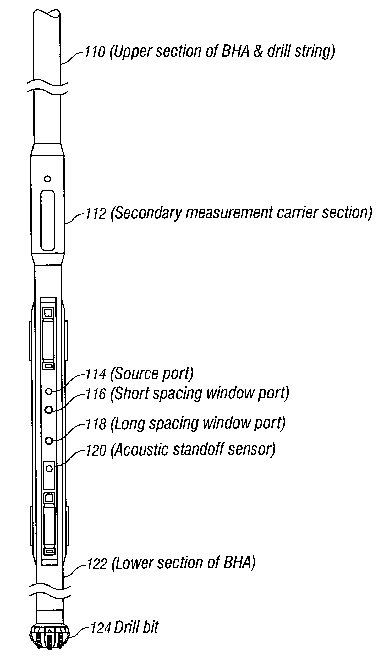
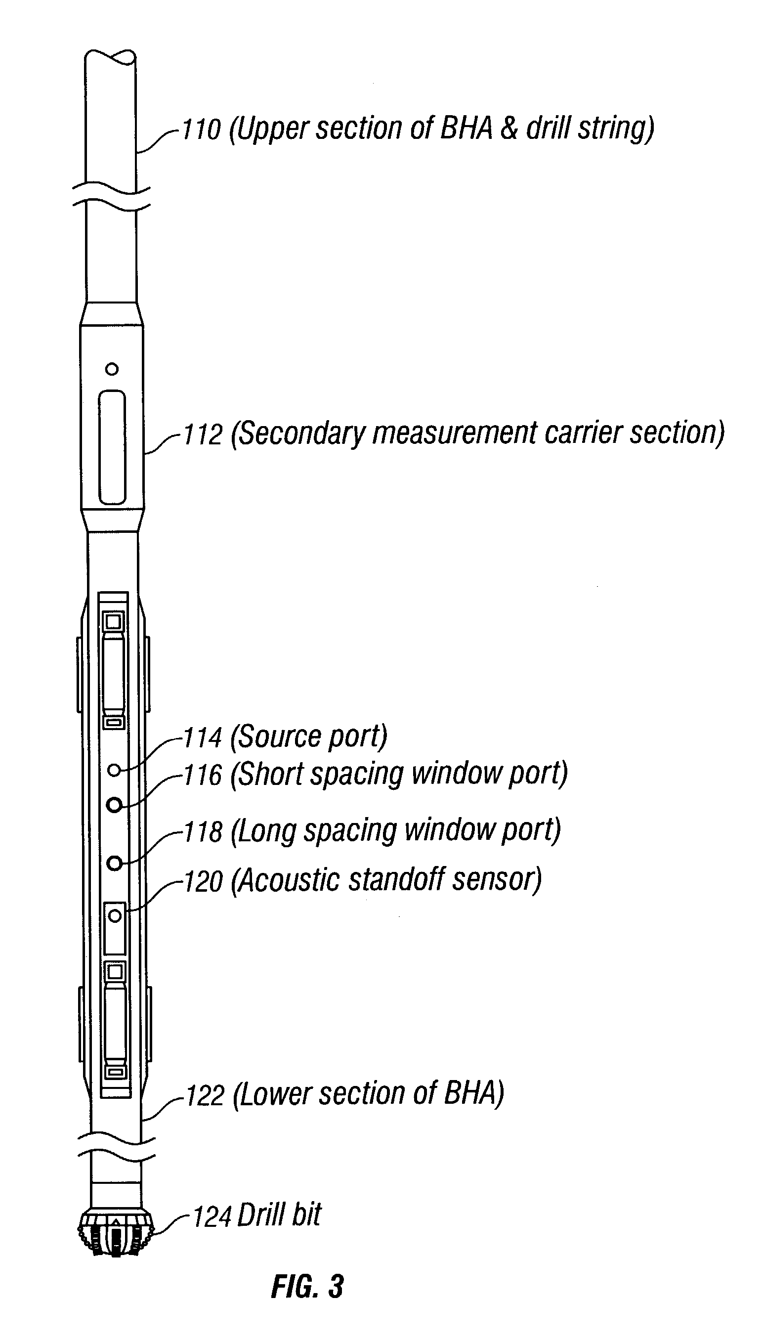
[0028]Referring now to FIG. 3 a diagram of the basic components for an exemplary gamma-ray density tool. This tool comprises an upper section of a bottom hole assembly including a drill collar 110. The logging tool of the present invention contains a gamma-ray source 114 and two spaced gamma-ray detector assemblies 116 and 118. All three components are placed along a single axis that has been located parallel to the axis of the tool. The detector 116 closest to the gamma-ray source will be referred to as the “short space detector” and the one farthest away 118 is referred to as the “long space detector”. Gamma-ray shielding (not shown) is located between detector assemblies 116, 118 and source 114. Windows (ports) open up to the formation from both the detector assemblies and the source. The acoustic caliper (A1) 120 is inline and close to the gamma detectors (LS & SS). A layer of drilling fluid (mud) is present between the formation and the detector assemblies and source. Also show...


PUM


Abstract

A logging-while-drilling density sensor includes a gamma ray source and at least two NaI detectors spaced apart from the source for determining measurements indicative of the formation density. An acoustic caliper is used for making standoff measurements of the NaI detectors. Measurements made by the detectors are partitioned into standoff bins. An adaptive spine and rib method uses the standoff measurements to obtain density estimates. The method of the invention may also be used with neutron porosity logging devices.

Description

CROSS-REFERENCES TO RELATED APPLICATIONS[0001]This application claims priority from U.S. Provisional Patent Application Ser. No. 60 / 369,758 filed on Apr. 3, 2002.BACKGROUND OF THE INVENTION[0002]1. Field of the Invention[0003]This invention relates generally to borehole logging apparatus and methods for performing nuclear radiation based measurements. More particularly, this invention relates to a new and improved apparatus for effecting formation density logging in real time using gamma rays in a measurement-while-drilling (MWD) tool.[0004]2. Background of the Art[0005]Oil well logging has been known for many years and provides an oil and gas well driller with information about the particular earth formation being drilled. In conventional oil well logging, after a well has been drilled, a probe known as a sonde is lowered into the borehole and used to determine some characteristic of the formations which the well has traversed. The probe is typically a hermetically sealed steel cyl...

Claims


Application Information

Patent Timeline
Patent Type & Authority Patents(United States)
IPC IPC(8): G01V5/14G01V5/10G01V5/12
CPCG01V5/125G01V5/107
Inventor SCHNEIDER, DAVID M.EFREMOV, SERGEY V.SALE, MATTHEW J.
Owner BAKER HUGHES INC
Learn More