Laser level

a laser level and laser technology, applied in the field of laser levels, can solve the problem that the laser level may be difficult to install on the wall, and achieve the effect of improving the laser level

Inactive Publication Date: 2006-11-14
BLACK & DECKER INC
View PDF76 Cites 45 Cited by
  • Summary
  • Abstract
  • Description
  • Claims
  • Application Information

AI Technical Summary

Problems solved by technology

Such laser level may be difficult to install on a wall, etc.

Method used


Image

  • Laser level
  • Laser level
  • Laser level

Examples


Embodiment Construction

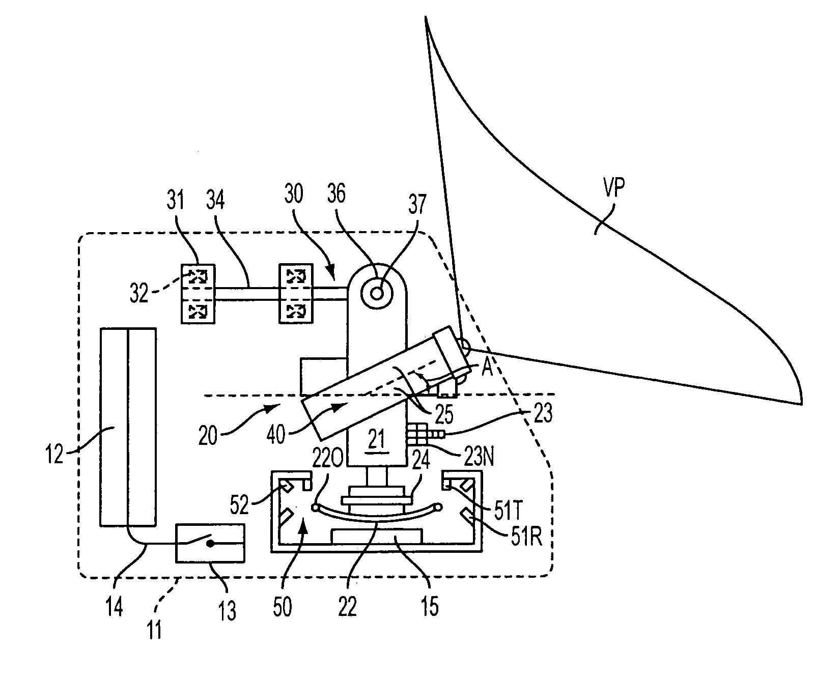
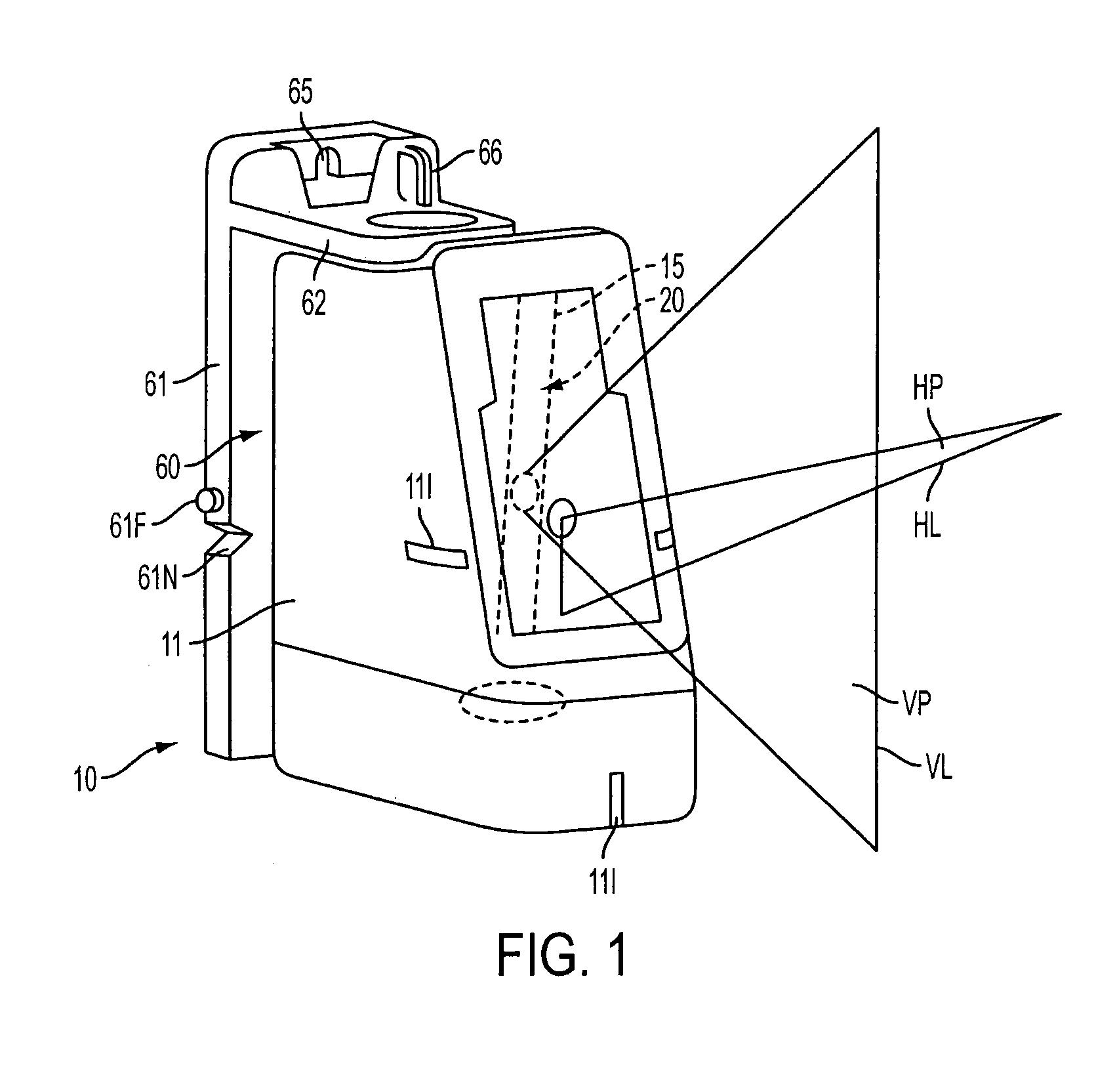
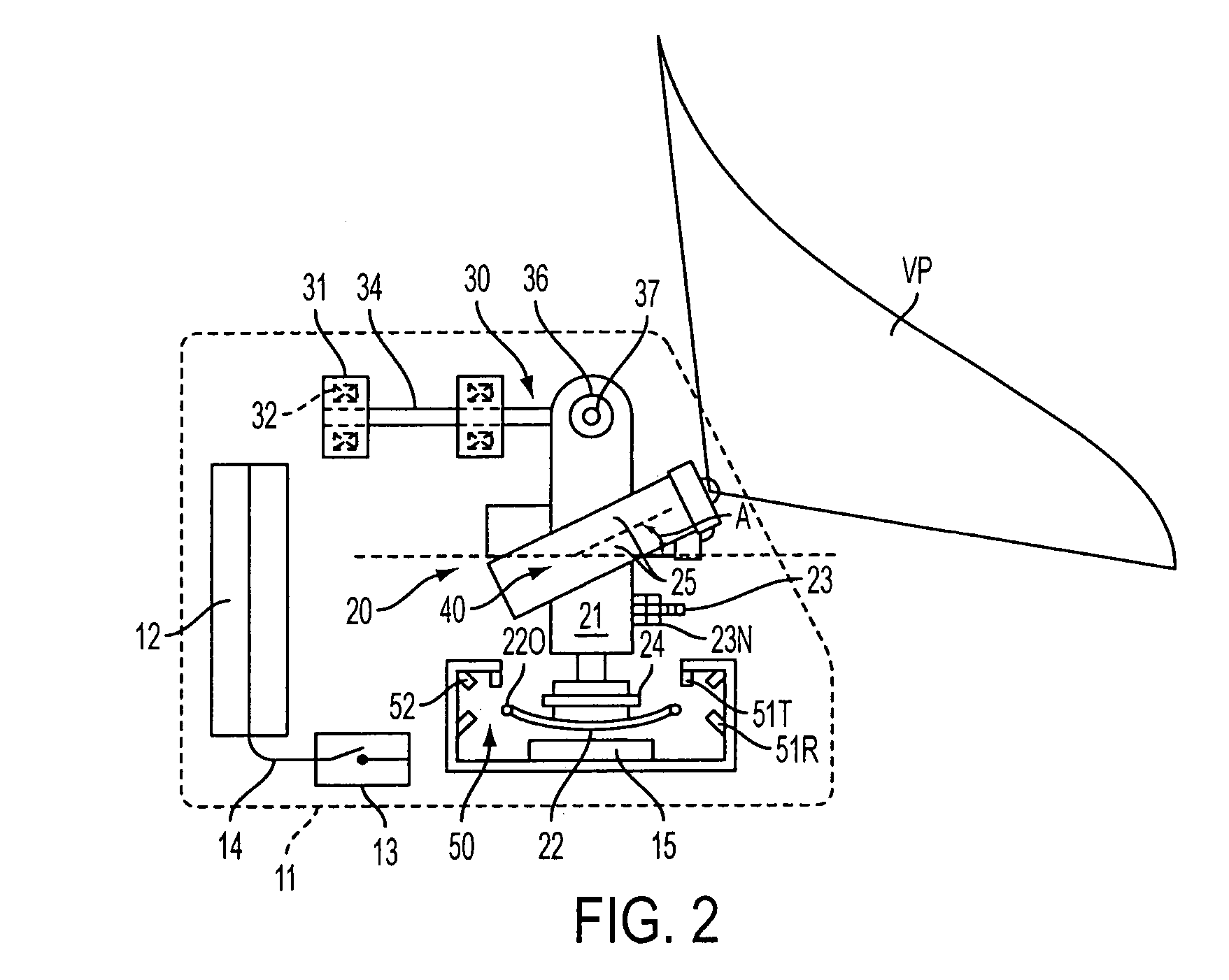
[0015]The invention is now described with reference to the accompanying figures, wherein like numerals designate like parts. Referring to FIGS. 1–2, a laser level 10 may have a housing 11, a pendulum assembly 20 hung inside the housing 11, and two line generating laser assemblies 40 disposed on the pendulum assembly 20. Each laser assembly 40 preferably generates a laser light plane so that, upon contact with a surface, such as a wall, a laser line is generated on the surface.

[0016]Preferably, one of the laser assemblies 40 is aligned so that it generates a horizontal planar beam HP, so that a horizontal line HL appears on the surface. Similarly, the other laser assembly 40 may be aligned to generate a vertical planar beam VP, so that a vertical line VL appears on the surface. Horizontal planar beam HP and / or vertical planar beam VP preferably exit housing 11 via a window 15 mounted unto housing 11.

[0017]Persons skilled in the art will recognize that, because the laser assemblies 40...


PUM

PropertyMeasurementUnit
angleaaaaaaaaaa
angleaaaaaaaaaa
gravityaaaaaaaaaa

Abstract

A laser level includes a housing, a pendulum pivotably mounted to the housing and a laser diode assembly disposed on the pendulum. A gimbal assembly is employed for pivotably mounting the pendulum to the housing. The gimbal assembly includes a frame connected to the housing, a first pair of bearings disposed on the frame, an axle extending through the first pair of bearings, a body disposed on the axle and pivotably supporting the pendulum, and a second pair of bearings disposed between the body and the pendulum. The first pair of bearings is disposed on one side of the second pair of bearings.

Description

CROSS-REFERENCE TO RELATED APPLICATIONS[0001]The following is a continuation-in-part of U.S. application Ser. No. 29 / 213,371, filed on Sep. 16, 2004 now U.S. Pat. No. D509,453, which is in turn a continuation of U.S. application Ser. No. 29 / 201,635, filed on Mar. 18, 2004, now U.S. Pat. No. D498,687.FIELD OF THE INVENTION[0002]This invention relates generally to laser levels and more specifically to a laser level which generates a laser line on a surface.BACKGROUND OF THE INVENTION[0003]U.S. Pat. No. 5,539,990, which is wholly incorporated herein by reference, discloses an optical levelling, plumbing and angle-calibrating instrument including a frame, a plumb body universally pendulously mounted on the frame and defining a vertical plumb line gravitationally, at least an illuminator electrically connected to a power supply and mounted on the plumb body for emitting laser light, and at least a cylindrical-surfaced lens mounted on the plumb body in front of the illuminator for planarl...

Claims


Application Information

Patent Timeline
Patent Type & Authority Patents(United States)
IPC IPC(8): G01C9/12G01C15/00
CPCG01C15/002G01C15/105G01C15/004Y10T29/49826
Inventor BASCOM, JAMES P.HORKY, JOHN K.MCKIBBEN, JOHNLOPANO, DANIEL N.HOWARD, GEOFFREY S.NELSON, MICHAEL A.WENIG, JOHN C.
Owner BLACK & DECKER INC
Why Eureka
Try Eureka