Vibration generator for seismic applications

a vibration generator and seismic technology, applied in seismology, geological measurements, instruments, etc., can solve the problems of logistical and also process-dependent disadvantages, unwieldy systems available on the market for field use, etc., and achieve the effect of precise velocity determination and loss of quality

Inactive Publication Date: 2006-11-14
INST FUR GEOWISS GEMEINSCHAFTSAUFGABEN
View PDF3 Cites 1 Cited by
  • Summary
  • Abstract
  • Description
  • Claims
  • Application Information

AI Technical Summary

Benefits of technology

[0008]The invention eliminates the disadvantages of prior art. The invention addresses the problem of providing a readily portable and easily wieldable vibration generator with which vibrations for geophysical explorations of near-surface subsoil structures can be carried out up to a depth of approximately 150 meters.
[0028]Due to the electric control and electromechanical transduction, the initial signal is reproducible to a high degree, such that a stacking of any number of signal excitations is possible without loss of quality. Through the correlation process, the exact time adjustment with the control signal and the motion behavior, tapped off by means of the acceleration pickups, can be attained such that, compared to the pulse method, a considerably more precise velocity determination is possible. Due to the time extension of the signal, with the excitation only small instantaneous forces occur, which permit a virtually destruction-free object investigation.

Problems solved by technology

However, the systems available on the market are unwieldy for use in the field due to their comparatively large weight (approximately 100 kg for a transverse wave exciter without supply unit).
Furthermore, the necessary supply with 220 or 110 V mains voltage or power generators leads to logistic and also process-dependent disadvantages due to possible inductive interference currents.

Method used


Image

  • Vibration generator for seismic applications
  • Vibration generator for seismic applications

Examples


Embodiment Construction

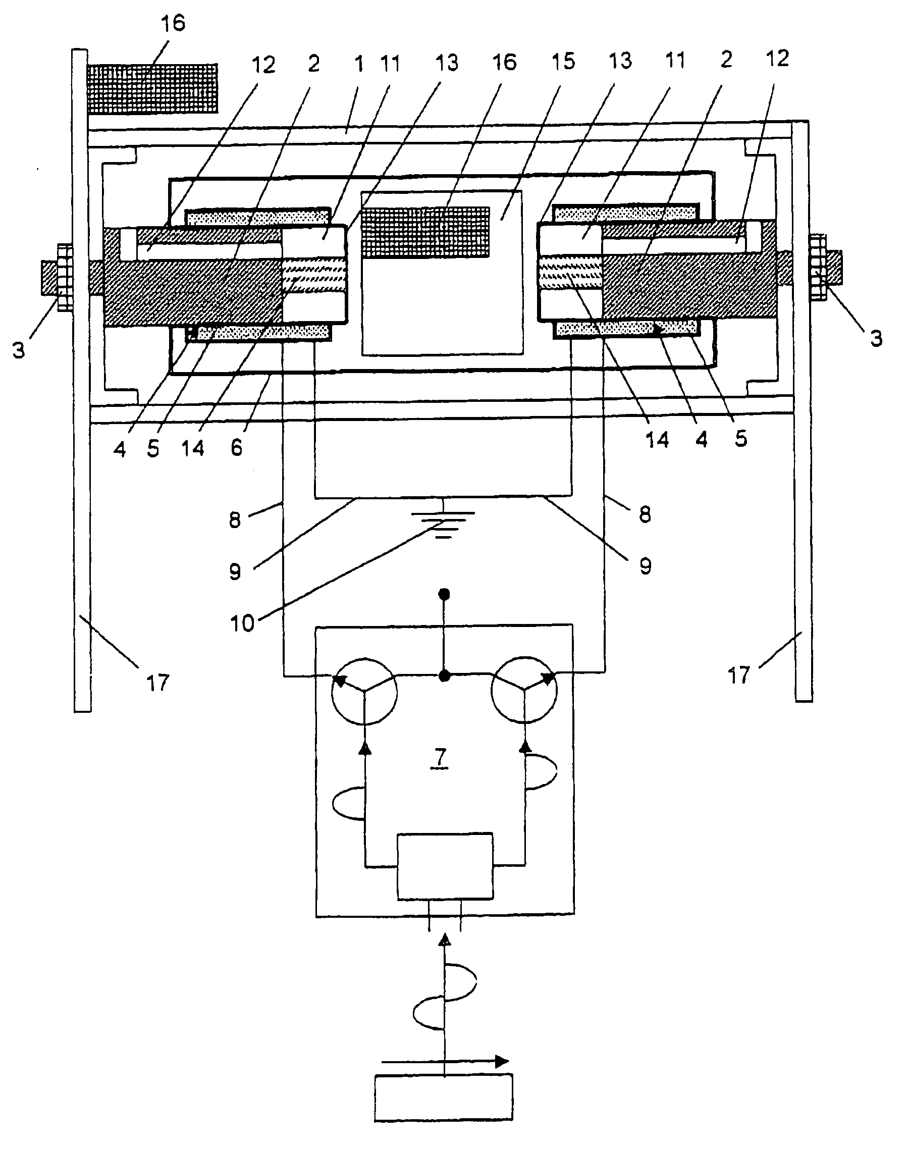
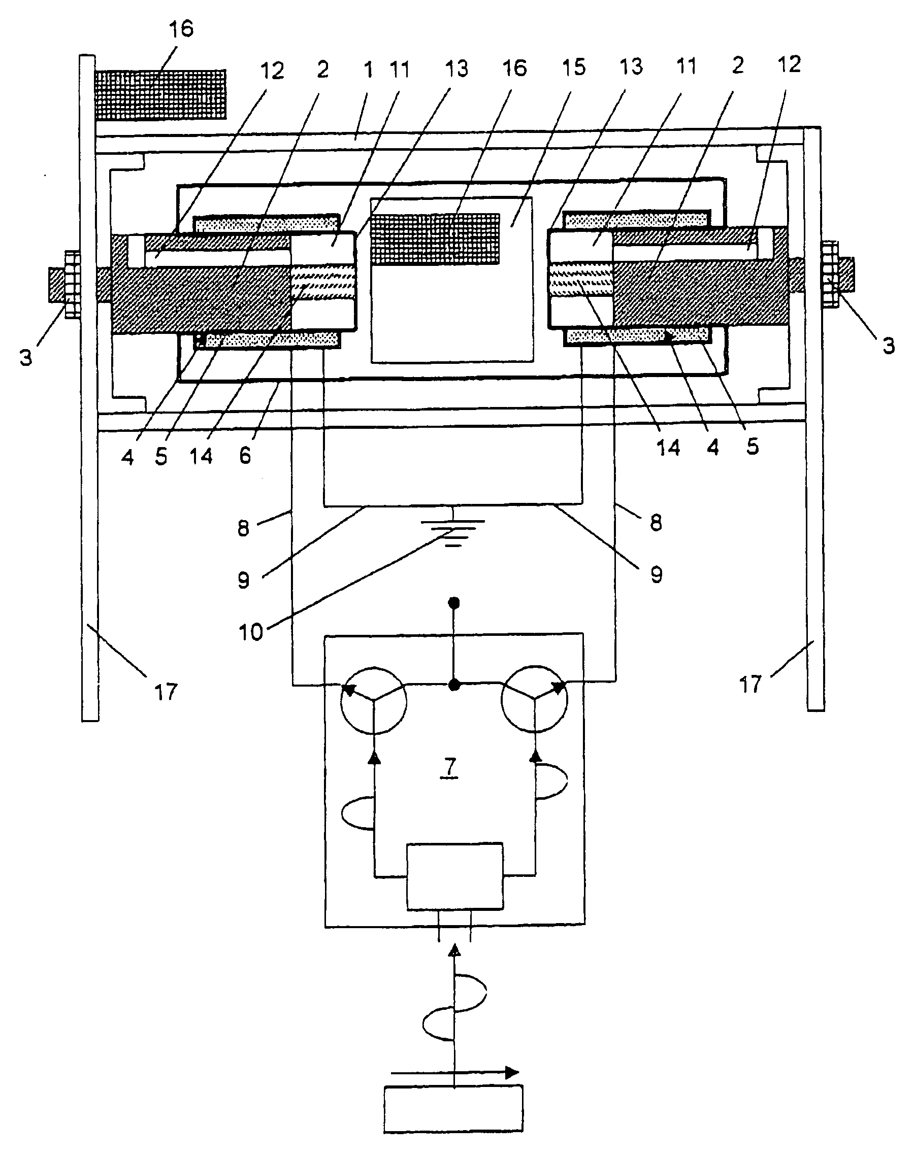
[0037]The device described in the following and depicted in the drawing makes possible the frequency-modulated excitation of transverse waves preferably in the frequency range of 1–300 Hz from a DC current energy source utilizing for example a commercially available 12 V car battery. At a net weight of approximately 5 kg, the device can be transported by one person without any problems.

[0038]In an outer housing 1 coil cores 2 are installed on opposing sides with the aid of bolted joints 3. On these coil cores 2 slide brass sleeves 4 which are encompassed by coils 5 and which are parts of the inner housing 6.

[0039]The coils 5 are activated from the control device 7 via electric lines 8 alternating in time. The coils 5 are both connected via one cable 9 each to the electrical ground 10.

[0040]As a component of the inner housing 6 the coils 5 vibrate continuously back and forth during operation. The hollow volumes 11, encompassed by the coils, into which extend the coil cores 2, must be...


PUM


Abstract

A vibration generator can be used for seismic applications, producing vibrations for exploration of near-surface subsoils up to 150 meters. Containing two coils activated with AC current or other electrical pulses, the generator is coupled to the object to be investigated by suitable elements. Inside is an inner housing, the outer housing movably supporting, on opposing sides, two coils connected through the inner housing. One coil is activated continuously and alternates with a positive wave component of an AC current control signal; at the same time the other coil alternates with a negative wave component. The result, a controlled vibratory motion, is also achieved with DC voltage. Because of the law of action and reaction, the vibratory motion passed to the coupling elements allows motion into the object being investigated. In contrast to conventional moving coil systems for electromechanical vibration transduction, this generator is based on a soft-metal magnetic instrument.

Description

BACKGROUND OF THE INVENTION [0001]1. Field of the Invention[0002]The invention relates to a vibration generator for seismic application comprising a housing, in which coils, activated with AC current or electric pulses, are accommodated and which is coupled via a coupling element to the investigation object.[0003]2. Description of the Related Art[0004]In raw material exploration seismic vibration methods for the geophysical exploring of deep subsoil structures and material properties are employed. For this purpose longitudinal and transverse waves are applied. The essential advantages of the method are the controllable signal, the high-grade reproducibility, the exact determination of the signal delay time and the damage and environtal endangerment which are low in comparison to pulse sources (for example explosives).[0005]The same methodology is also suitable for exploring near-surface subsoil of up to a few hundred meters depth for geophysical engineering tasks. However, as a rule...

Claims


Application Information

Patent Timeline
Patent Type & Authority Patents(United States)
IPC IPC(8): G01V1/04G01V1/053
CPCG01V1/053
Inventor POLOM, ULRICH
Owner INST FUR GEOWISS GEMEINSCHAFTSAUFGABEN
Why Eureka
Try Eureka