Impact cutoff

a cutting-off and impact technology, applied in the direction of forging/pressing/hammering apparatus, metal-working feeding device, handling device, etc., can solve the problems of loss of cutoff accuracy and quality, fatigue failure of various cutter parts, etc., to reduce impact induced vibration, reduce the effect of cutting accuracy and quality, and simple, reliable and durable design

Active Publication Date: 2018-08-28
THE NAT MASCH CO
View PDF12 Cites 0 Cited by
  • Summary
  • Abstract
  • Description
  • Claims
  • Application Information

AI Technical Summary

Benefits of technology

[0005]The invention provides an impact cutoff device for a progressive high speed cold former that is simple, reliable, and durable in design. The device is characterized by a low mass rigid cutter carriage, a torsion spring for carriage return, and an articulated, oil lubricated and dampened carriage drive block on a pivoting drive lever. These features reduce impact induced vibration otherwise leading to fatigue failure and wear of the various cutter parts and consequent loss of cutoff accuracy and quality.

Problems solved by technology

These features reduce impact induced vibration otherwise leading to fatigue failure and wear of the various cutter parts and consequent loss of cutoff accuracy and quality.

Method used


Image

  • Impact cutoff
  • Impact cutoff
  • Impact cutoff

Examples


Embodiment Construction

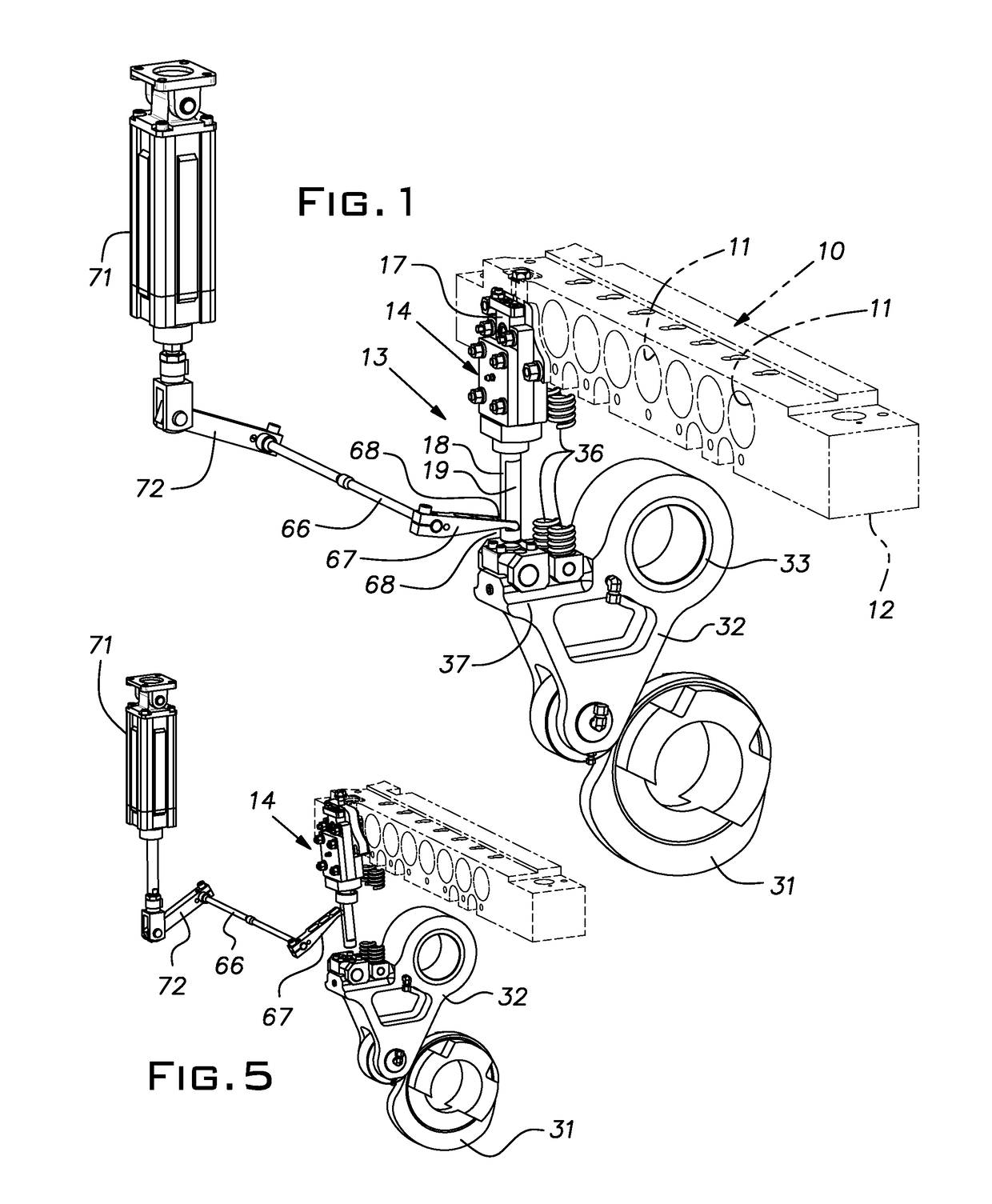
[0014]A progressive cold forming machine is schematically illustrated at 10 in FIG. 1. For clarity, only a few selected components of the machine 10 are illustrated. A series of die stations 11 of a bolster 12 are evenly spaced in a horizontal array. A ram or slide, not shown, reciprocates towards and away from the bolster while carrying a horizontal array of punches or tools on centers corresponding to the die stations 11. As is customary, a transfer device (not shown) transfers a blank from one die station 11 to a successive one as the blank is progressively formed into a finished or nearly finished part. A cutoff device 13 of the invention is adjacent a first one of the die stations 11. The cutoff device 13 receives round wire and shears it into separate blanks of uniform length. The transfer device in a known manner picks up a sheared blank and moves it to the first die station. With reference to FIGS. 6-8, the cutoff device 13 includes a cutter pack or cartridge 14. The cutter ...


PUM

PropertyMeasurementUnit
velocityaaaaaaaaaa
speedaaaaaaaaaa
speedaaaaaaaaaa

Abstract

An impact cutoff device for a progressive high speed cold former having a low mass rigid cutter carriage, a torsion spring for carriage return, and an articulated, oil lubricated and dampened carriage drive block on a pivoting drive lever serving to reduce impact induced vibration otherwise leading to fatigue failure and wear of the various cutter parts and consequent loss of cutoff accuracy and quality.

Description

BACKGROUND OF THE INVENTION[0001]The invention relates to blank cutoff apparatus for progressive cold forming machines.PRIOR ART[0002]For cutting wire and bar stock, it is common to use enclosed circular sleeves as cutter blades, one movable with a cutter carriage (cutter) and the other fixed (quill). Reducing the diametrical clearance in the cutter blades is known to improve the quality of cutoff as well as to maintain control of the blank after it has been sheared.[0003]With minimal clearance between the cutting or shearing blades and the wire, and because the wire shears at the very beginning of the shearing motion, there is minimal distance for a cutter carriage to accelerate to a significant velocity. Thus, most high velocity cutter mechanisms accelerate a driving member to the desired velocity prior to engaging the cutter carriage.[0004]Prior art impact blank cutoff devices have often been complicated, have required a high level of maintenance, and have exhibited early wear.SU...

Claims


Application Information

Patent Timeline
Patent Type & Authority Patents(United States)
IPC IPC(8): B23D23/00B21K27/06B26D3/16B26D5/16
CPCB23D23/00B26D5/16B21K27/06B26D3/16B21D28/14B21F11/00B21D43/28B23D15/04B23D15/12B23D35/001
Inventor HALL, AARON T.
Owner THE NAT MASCH CO
Why Eureka
Try Eureka