Decoder and method for decoding encoded input data containing a plurality of blocks or packets

a decoding and input data technology, applied in the field of decoding devices, can solve the problems of reducing the degree of data compression, demanding video, and requiring images and videos to communicate, and achieve the effect of reducing image quality

Active Publication Date: 2017-01-03
GURULOGIC MICROSYST
View PDF41 Cites 0 Cited by
  • Summary
  • Abstract
  • Description
  • Claims
  • Application Information

AI Technical Summary

Benefits of technology

The present invention provides a decoder and method for efficiently decoding and decompressing encoded input data of at least one image without any significant loss of image quality. The technical effect is that translated or compressed data can be accurately and easily recovered without compromising the quality of the original image.

Problems solved by technology

However, such images and videos are demanding in respect of data memory capacity and communication system bandwidth utilized.
When communication system bandwidth is limited, such images and videos take significant time to communicate.
However, it is highly desirable that encoding methods that provide a degree of data compression should be substantially lossless in relation to information content when generating the compressed data.
In general, known video codecs are not able to code efficiently extensive areas of images with substantially constant parameters whilst concurrently being able to encode highly spatially detailed areas of the images.
Such relatively smaller blocks are employed because larger sizes of blocks result in inefficient encoding processes, although 16×16 image element blocks are sometimes employed.
Certain types of contemporary encoding can even results in an increase in data size, when error correction features such as parity codes and error correction codes are included.

Method used


Image

  • Decoder and method for decoding encoded input data containing a plurality of blocks or packets
  • Decoder and method for decoding encoded input data containing a plurality of blocks or packets
  • Decoder and method for decoding encoded input data containing a plurality of blocks or packets

Examples


an example

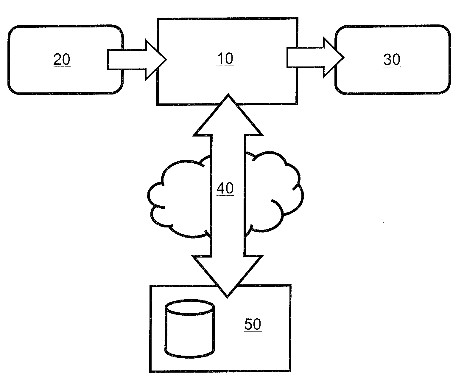
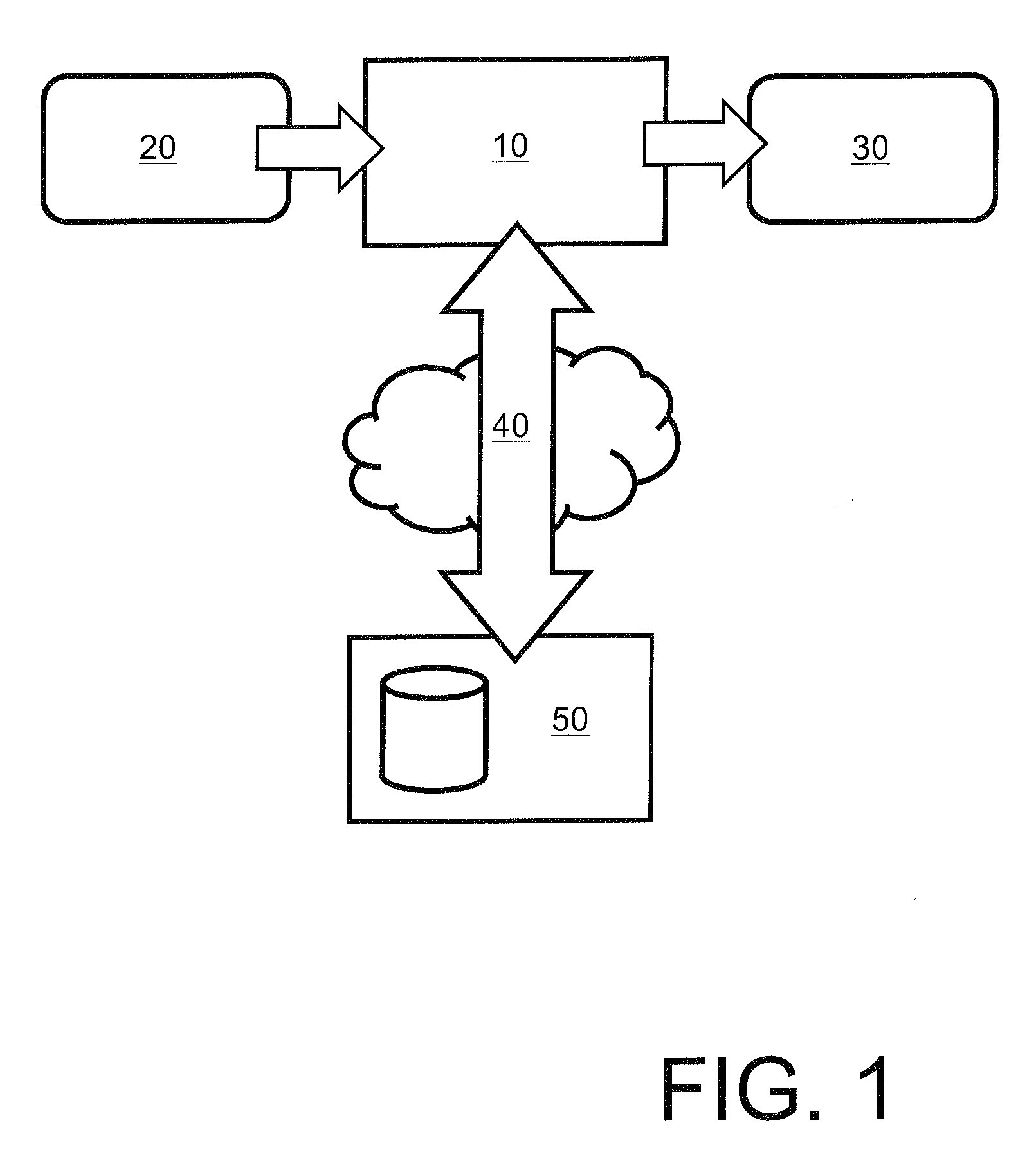
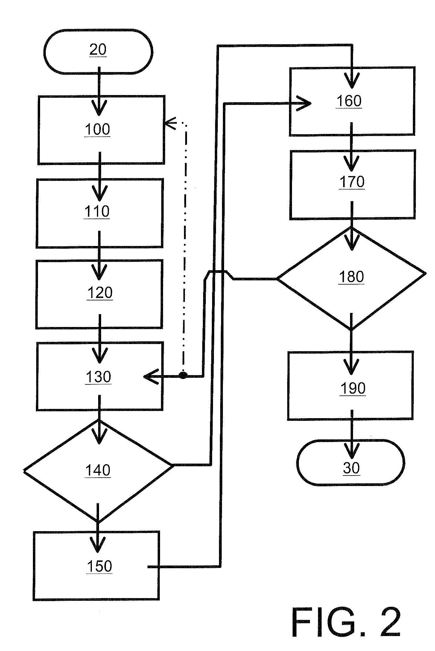
[0086]Simplified example of decoding an encoded image is described. Based on embodiment decoder receives information content from encoder (for example as streamed or as file).

[0087]According to example the information content is in form of file consisting of following information fields and content:

[0088]

Imagesize: 120 × 80 pixelsInitialBlocksize: 40 × 40 pixelsSplitBit: 0 0 1 0000 0 1 0010 0000 1 1000 0000MethodBits: 0 0 1 0 0 0 0 0 0 0 0 0 0 0 0 0 0 0 0 0 0Values: 10 10 20 25 15 20 10 10 10 10 10 10 5 10 5 5 5 5 5 5 10 5 5 5

[0089]Where:

[0090]Imagesize describes the size of the image to be decoded. The size of the image can be arbitrary;

[0091]InitialBlocksize describes what is size of “basic” initial blocks. Depending on the implementation the InitialBlocksize can be fixed (such as 40×40) or it can vary (20×20, 80×80 etc). It might not be needed to send Initialblocksize information in case using default values in decoder and encoder;

[0092]SplitBit values of “0” indicate that said b...


PUM


Abstract

A decoder which decodes input data to generate corresponding decoded output data is operable:(a) to process encoded input data to extract header information indicative of encoded data pertaining to blocks and / or packets included in the encoded input data, the header information including data indicative of transformations employed to encode and compress original block and / or packet data for inclusion as the encoded data pertaining to the blocks and / or packets;(b) to prepare a data field in a data storage arrangement for receiving decoded block and / or packet content;(c) to retrieve information describing the transformations and then applying an inverse of the transformations for decoding the encoded and compressed original block and / or packet data to generate corresponding decoded block and / or packet content for populating the data field; and(d) when the encoded input data has been at least partially decoded, to output data from the data field as the decoded output data.

Description

CROSS REFERENCE TO RELATED APPLICATION[0001]This application claims priority from U.K. Application Serial No. GB 1214400.2 filed Aug. 13, 2012, the entire contents of which is incorporated herein by reference.FIELD OF THE INVENTION[0002]The present invention relates to decoders for receiving encoded input data and decoding the input data to generate corresponding decoded output data. Moreover, the present invention also concerns methods of decoding encoded input data to generate corresponding decoded output data. Furthermore, the present invention also concerns software products recorded on machine-readable data storage media, wherein the software products are executable upon computing hardware for implementing aforesaid methods.BACKGROUND OF THE INVENTION[0003]Images and videos are stored and communicated to an increasing extent by contemporary human population, for example multimedia content via Internet and wireless communication networks. The images and videos are stored and com...

Claims


Application Information

Patent Timeline
Patent Type & Authority Patents(United States)
IPC IPC(8): H04N11/02H04N21/439H04N21/44H04N21/4402H04N19/157H04N19/12H04N19/46H04N19/169
CPCH04N21/4402H04N19/12H04N19/157H04N19/188H04N19/46H04N21/4394H04N21/44008H04N19/61H04N19/96H04N7/24H04N19/00H04N19/60H04N19/44
Inventor KALEVO, OSSIKARKKAINEN, TUOMAS
Owner GURULOGIC MICROSYST
Why Eureka
Try Eureka