Method, computer and magnetic resonance apparatus for controlling shimming of the basic magnetic field

a magnetic resonance and basic magnetic field technology, applied in the field of actuating shimming in the magnetic resonance apparatus, can solve the problems of unwanted eddy current fields in the reception volume of the magnetic resonance sequence, large deviations, and acquisition of lower-quality magnetic resonance image data

Active Publication Date: 2019-09-03
SIEMENS HEALTHCARE GMBH
View PDF15 Cites 0 Cited by
  • Summary
  • Abstract
  • Description
  • Claims
  • Application Information

AI Technical Summary

Benefits of technology

[0018]In this context, the synchronization of the actuation of the shim coil arrangement and the activation of the gradient pulse shape can be of particular importance. In this context, the synchronization can be ensured by the generation of the shim settings being triggered by the provision and modification of the gradient pulse shape to be activated. Therefore, the shim settings are not generated independently of the gradient pulse shape to be activated, but can be derived directly from the pulse shape to be activated. Therefore, there is a direct electronically and / or digitally implemented path, which generates shim settings out of a gradient pulse shape prepared for activation, by a modification of the gradient pulse shape with which the shim coil arrangement can be actuated during the activation of the gradient pulse shape. This enables eddy currents generated by the activation of the gradient pulse shape to be automatically compensated by the shim coil arrangement. The magnetic resonance sequence used for the magnetic resonance imaging thus can remain unchanged; i.e. no adaptation of the magnetic resonance sequence is necessary.
[0019]The inventive procedure thus can result in an efficient suppression of eddy currents caused by gradient circuits. This enables the quality of the magnetic resonance image data acquired in the magnetic resonance imaging to be increased or artifacts in the magnetic resonance image data to be avoided. This also enables gradient coils found to have a higher deviation from a desired shape in the in-process inspection and testing still to be delivered to the customers instead of being destroyed.
[0021]In another embodiment, the modification of the gradient pulse shape and the generation of the shim settings using the modified gradient pulse shape are implemented such that second-order eddy current contributions that occur during the activation of the gradient pulse shape by the gradient coil arrangement are at least partially compensated by the shim settings used for the actuation of the shim coil arrangement. In this embodiment, the modification of the gradient pulse shape can involve the formation of the time derivative of the gradient pulse shape. The inventive procedure can be used to suppress the second-order eddy current contributions. In this way, it is precisely in marginal regions of the reception volume that a significant improvement of the image quality can be achieved, since the second-order eddy current fields typically influence the magnetic resonance image data proportionally to the square of the radius at high radial positions in the reception volume. Hence, the suggested compensation enables a large reception volume to be used for the acquisition of the magnetic resonance image data without any loss of image quality. This can, for example, be in the case of shoulder imaging. It is possible for not only typical integral terms to be compensated in the second-order eddy current field, such as field terms along the z-axis (A(2,0) terms), along the x-axis (A(2,1) terms) or along the y-axis (B(2,1) terms), but also additional cross terms, such as B(2,2) terms.
[0024]The control computer according to the invention for a magnetic resonance apparatus comprises a gradient controller, a shim controller and an interface between the gradient controller and the shim controller. The interface is designed to receive a gradient pulse shape from the gradient controller, to modify the gradient pulse shape and to transfer the modified gradient pulse shape to the shim controller. The interface can be an electronic connection or an interface between the gradient controller and the shim controller. Hence, the interface can be an input component, which receives the gradient pulse shape from the gradient controller. The interface can be a modification component, which modifies the gradient pulse shape. The interface also may be an output component, which transmits the modified gradient pulse shape to the shim controller. Hence, the interface can enable automatic actuation of the shim coil arrangement, which is triggered by the provision of a gradient pulse shape by the gradient controller. Hence, the control computer according to the invention can enable the above-described automatic compensation of the eddy current fields generated by the activation of the gradient pulse shape. It is also possible for the inventive shim coil arrangement simultaneously to be used for dynamic shimming, as is known to those skilled in the art with which inhomogeneities, in particular second-order inhomogeneities, can be compensated on a slice-by-slice basis, or respiratory influences or other dynamic disturbances can be compensated in real time. The shim setting time for static shim settings can also be reduced for time-critical procedures.
[0026]In another embodiment, of the control computer the interface has control components that enable the transfer of the modified gradient pulse shape to the shim controller in real time during the actuation of the gradient coil arrangement by the gradient controller. Hence, the shim controller can be actuated with the modified gradient pulse shape at the same speed as the gradient coil arrangement is actuated with the gradient pulse shape by the gradient controller. Hence, the shim controller or the shim coil arrangement can perform a particularly advantageous compensation of the eddy currents that occur during the operation of the gradient coil arrangement.
[0028]In another embodiment of the magnetic resonance apparatus, the gradient controller and the shim controller are matched to one another such that the actuation of the shim coil arrangement takes place during the actuation of the gradient coil arrangement by the gradient pulse shape. The synchronization of the shim controller and the gradient controller enables the compensation of the eddy currents caused by the operation of the gradient coil arrangement by the shim coil arrangement.

Problems solved by technology

Even small deviations in homogeneity can result in large deviations in the frequency distribution of the nuclear spins, so that lower-quality magnetic resonance image data are acquired.
The emission of specific gradient pulse shapes, defined by specifications of the magnetic resonance sequence, by the gradient coils of the scanner can result in unwanted eddy current fields in a reception volume of the magnetic resonance sequence.
The eddy current fields that occur in the reception volume can result in a loss of quality of the magnetic resonance images acquired by the magnetic resonance sequence.
For example, with certain magnetic resonance sequences, fat suppression can be impaired by the eddy current fields.
Although a typical gradient coil arrangement of a magnetic resonance apparatus is designed to ensure the eddy currents caused by the operation of the gradient coils thereof, and hence the eddy current fields in the reception volume of the magnetic resonance sequence, are minimized, production tolerances during the manufacture of the gradient coils can result in a deviation from the desired shape of the actual conductor path of the gradient coil in the conductor guide.
A shift of this kind can result in a loss of symmetry of the conductor guide in the gradient coil arrangement and hence produce integral terms in the gradient field and eddy current field of the gradient coil arrangement.
While the disruptive terms in the gradient field can typically be ignored, it not usually possible to ignore the integral terms in the eddy current field of the gradient coil arrangement.

Method used


Image

  • Method, computer and magnetic resonance apparatus for controlling shimming of the basic magnetic field
  • Method, computer and magnetic resonance apparatus for controlling shimming of the basic magnetic field

Examples


Embodiment Construction

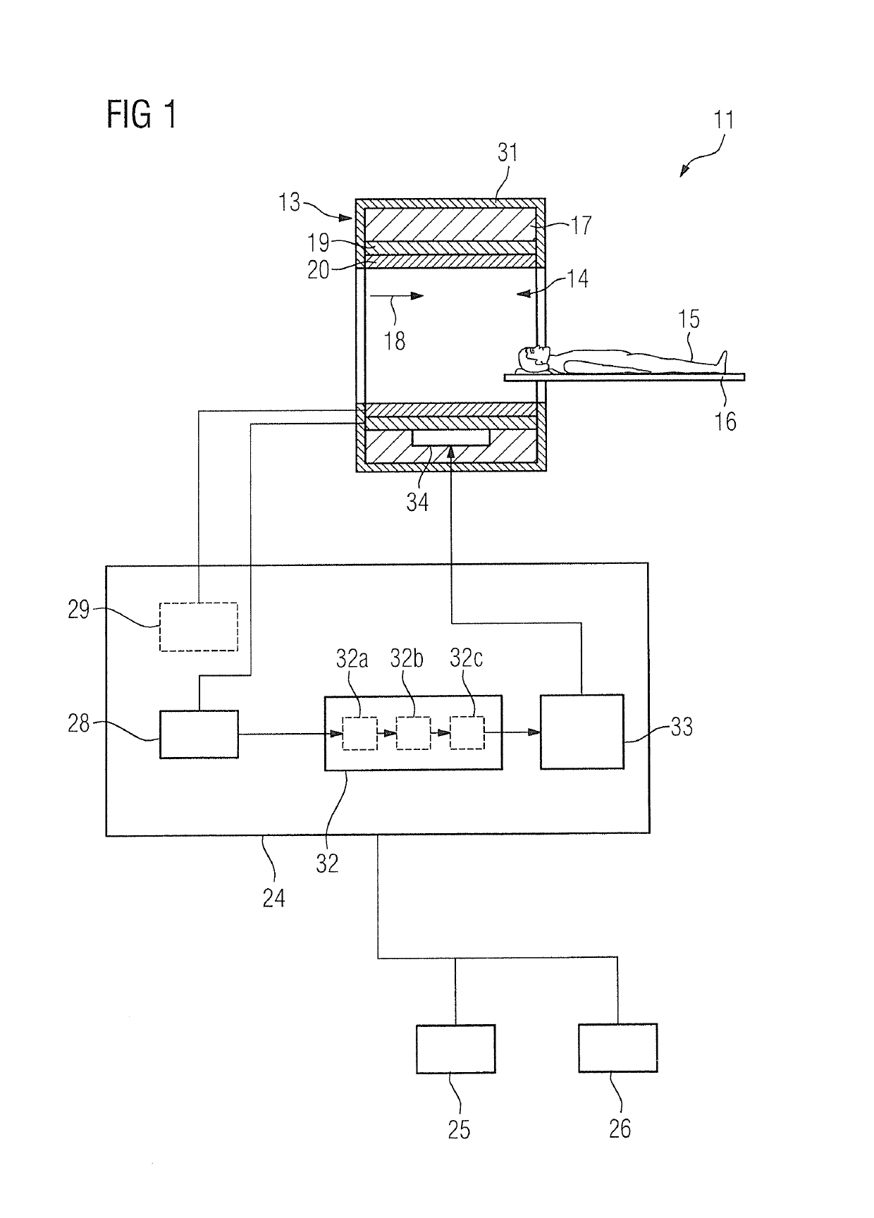
[0036]FIG. 1 is a schematic view of a magnetic resonance apparatus according to the invention with a control computer according to the invention.

[0037]The magnetic resonance apparatus 11 has a scanner 13 with a basic field magnet 17 for generating a strong and constant basic magnetic field 18. In addition, the scanner 13 has a cylindrical patient-receiving region 14 for receiving an object under examination 15, in the present case a patient, wherein the patient-receiving region 14 is cylindrically surrounded by the scanner 13 in a circumferential direction. The patient 15 can be moved into the patient-receiving region 14 by a patient support 16 of the magnetic resonance apparatus 11. To this end, the patient support 16 has an examination table that is moveable within the scanner 13. The scanner 13 is shielded from the outside by a housing shell 31.

[0038]The scanner 13 also has a gradient coil arrangement 19 for generating magnetic field gradients that are used for spatial encoding d...


PUM


Abstract

In a method for actuating a shim coil arrangement of a magnetic resonance data acquisition scanner that has a shim controller that operates said shim coil arrangement, and a gradient coil arrangement operated by a gradient controller, the gradient controller determine a gradient pulse shape, in accordance with specifications of a magnetic resonance data acquisition sequence, that is activated by the gradient coil arrangement, when the sequence is executed in said scanner. A modifies the gradient pulse shape and provides the modified gradient pulse shape to the shim controller and the shim controller generates shim settings dependent on the modified gradient pulse shape, and actuates said shim coil arrangement according to the shim settings during activation of the gradient pulse shape by the gradient coil arrangement during execution of the sequence in said scanner.

Description

BACKGROUND OF THE INVENTION[0001]Field of the Invention[0002]The invention concerns a method for actuating shimming in a magnetic resonance apparatus, as well as a control computer and magnetic resonance apparatus designed to implement such a method.[0003]Description of the Prior Art[0004]In a magnetic resonance (MR) apparatus, also called a magnetic resonance tomography system, a subject to be examined, in particular the body of a patient, is exposed to a relatively strong basic magnetic field with the use of a basic field magnet, for example 1.5 or 3 or 7 tesla. In addition, gradient pulses are activated by a gradient coil arrangement. A radio-frequency antenna also emits high-frequency radio-frequency pulses, for example excitation pulses, from suitable radiators that cause the nuclear spins of specific atoms excited to resonance by these radio-frequency pulses to be tilted by a defined flip angle relative to the magnetic field lines of the basic magnetic field. Upon relaxation o...

Claims


Application Information

Patent Timeline
Patent Type & Authority Patents(United States)
IPC IPC(8): G01R33/3875G01R33/54G01R33/565
CPCG01R33/543G01R33/3875G01R33/56518G01R33/56563
Inventor DEWDNEY, ANDREWEBERLEIN, EVAKRUG, ANDREAS
Owner SIEMENS HEALTHCARE GMBH
Why Eureka
Try Eureka