A Yarn Leading System and Using Method for Enhancing the Antibacterial and Adsorption Functions of Yarn

A yarn and yarn-leading technology, which is applied in the direction of yarn, spinning machine, open-end spinning machine, etc., can solve the problems of structural restrictions, difficulty, difficult yarn, etc., and achieve the effect of stable structure and good washing resistance

Active Publication Date: 2022-05-06
HUBEI FENGSHU THREAD MFG +1
View PDF4 Cites 0 Cited by
  • Summary
  • Abstract
  • Description
  • Claims
  • Application Information

AI Technical Summary

Problems solved by technology

However, these two methods have restrictions on the types of yarns and yarn structures, and it is difficult to apply them in air-jet vortex spinning, which makes it impossible to enhance the antibacterial function on the basis of ensuring the existing advantages of air-jet vortex spinning
In addition, on the basis of not being able to realize the antibacterial function, it is more difficult to endow the yarn prepared by air-jet vortex spinning with new functions, such as adsorption function

Method used


Image

  • A Yarn Leading System and Using Method for Enhancing the Antibacterial and Adsorption Functions of Yarn
  • A Yarn Leading System and Using Method for Enhancing the Antibacterial and Adsorption Functions of Yarn
  • A Yarn Leading System and Using Method for Enhancing the Antibacterial and Adsorption Functions of Yarn

Examples


Embodiment 1

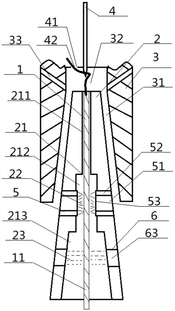
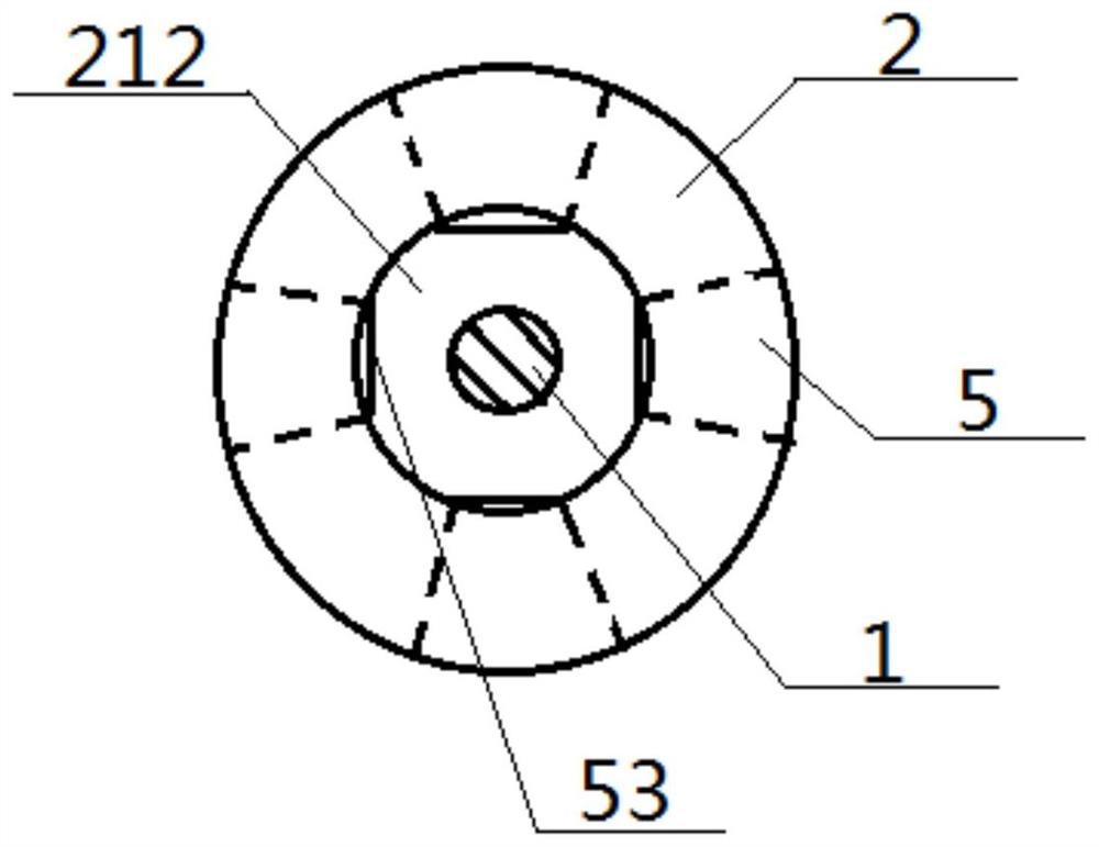
[0055] see figure 1 — Image 6 , a yarn drawing system for enhancing the antibacterial and adsorption function of the yarn, comprising a yarn drawing tube 2 and a vortex tube 3, and an exhaust passage 31 is sandwiched between the side wall of the yarn drawing tube 2 and the inner wall of the vortex tube 3, The middle part of the yarn drawing tube 2 is provided with a yarn drawing channel 21, and the top of the yarn drawing tube 2 is provided with a vortex chamber 32 that communicates with the yarn drawing channel 21. Directly above the chamber 32 is provided a guide needle 4 which is opposite to the yarn guiding channel 21, and a fiber channel 41 is arranged beside the guiding needle 4; the yarn guiding tube 2 is a truncated cone structure, and the yarn guiding channel 21 includes the upper channel 211 for threading, the middle channel 212 for threading, and the lower channel 213 for threading that are communicated in turn, and at least one negative powder spraying device 5 i...

Embodiment 2

[0058] The basic content is the same as that of Example 1, except that:

[0059] The solute of the Yin mist is any one of polypropylene-based hydrochloride, chitosan, polydivinyl propyl dimethyl ammonium chloride, polyethylene imine, polyquaternary ammonium salt, polyvinyl pyridine or any mix;

[0060] The solute of the yang water mist is any one or any mixture of sodium alginate, hyaluronic acid, polyacrylic acid, polystyrene sulfonic acid, polyvinyl sulfonic acid, and polyvinyl phosphoric acid.

Embodiment 3

[0062] The basic content is the same as that of Example 1, except that:

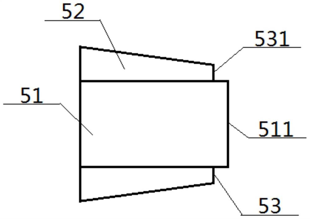
[0063] The powder spray pipe 52 is sleeved on the outside of the Yin liquid spray pipe 51, and the distance between the front end of the powder spray pipe 52 and the channel 212 in the yarn drawing is greater than the distance between the front end of the Yin liquid spray pipe 51 and the channel 212 in the yarn drawing, The side wall of the powder nozzle 52 is gradually increasing along the connecting line between the front end of the powder nozzle 52 and the rear end of the powder nozzle 52; The powder outlet 53 is formed, and the width of the powder outlet 53 is smaller than the radius of the anion liquid nozzle 51 .


PUM


Abstract

A yarn-drawing system that enhances the antibacterial and adsorption functions of yarns, comprising a yarn-drawing tube and a vortex tube, a yarn-drawing channel is opened in the middle of the yarn-drawing tube, and the yarn-drawing channel includes upper, middle and lower channels connected in sequence , at least one negative powder spraying device is arranged in the position surrounding the passage in the yarn leading on the yarn drawing tube, the negative powder spraying device includes a negative liquid spray pipe and a powder spray pipe, and the front ends of the negative liquid spray pipe and the powder spray pipe all extend to the middle passage of yarn drawing; the part surrounding the lower passage of yarn drawing on the said yarn drawing tube is provided with a positive liquid spraying ring, the positive liquid spraying ring is arranged around the lower passage of yarn drawing, and at least one positive liquid is arranged in the positive liquid spraying ring Nozzle, the front end of the yang liquid nozzle communicates with the yarn-drawing lower channel. This design not only enables the air-jet vortex yarn to have both antibacterial and adsorption functions, but also has a better spraying effect, can avoid the generation of droplets, and has higher quality.

Description

technical field [0001] The invention relates to a yarn-making process with increased antibacterial and adsorption functions, belonging to the technical field of online textiles, and in particular to a yarn drawing system and a method of use for enhancing the antibacterial and adsorption functions of yarns. Background technique [0002] Air-jet vortex spinning is a new type of spinning technology developed from air-jet spinning. During production, a two-phase structure air-jet vortex yarn consisting of core fibers and wrapping fibers is formed, which has high production efficiency. However, the existing air-jet vortex spinning The function of vortex spinning yarn is single, and the antibacterial and antibacterial effects are not good. [0003] At present, the preparation methods of antibacterial yarns mainly include two categories: the first category is the modification of fiber materials, mainly by chemically grafting functional polymers to the fiber surface, or loading func...

Claims


Application Information

Patent Timeline
Patent Type & Authority Patents(China)
IPC IPC(8): D01H4/02D02G3/44D02G3/38
CPCD01H4/02D02G3/449D02G3/38D10B2401/13
Inventor 陈晓林张如全武继松李建强朱文清
Owner HUBEI FENGSHU THREAD MFG
Why Eureka
Try Eureka