Dental impression dam system

a dental impression and dam technology, applied in the field of dental impression dam systems, can solve the problems of choking or choking the user or patient, overflowing of dental impression material, choking or choking the patient, etc., and achieve the effect of excellent dental impression and detailed dental impression

Inactive Publication Date: 2006-11-21
ROETZER PATRICK L
View PDF12 Cites 6 Cited by
  • Summary
  • Abstract
  • Description
  • Claims
  • Application Information

AI Technical Summary

Benefits of technology

The present invention provides a dental impression tray dam system that prevents dental impression material from moving too far back into the patient's mouth during use. This results in better quality dental images for both edentulous (no teeth) and dentulous (some teeth) areas. Additionally, this system helps achieve more precise details when taking dental impressions in specific areas such as the second and third molars. It also reduces or eliminates air bubbles in these areas.

Problems solved by technology

This patent describes a new dental impression dam system designed to solve the issue of excess dental impression material causing discomfort or danger to patients. Previous solutions such as dams only prevented the material from moving too far down the tongue but did not stop it from forming layers out of reach. A more effective solution is needed to ensure safe and comfortable dental procedures.

Method used


Image

  • Dental impression dam system
  • Dental impression dam system
  • Dental impression dam system

Examples


Embodiment Construction

[0032]Various aspects of the present invention will evolve from the following detailed description of the preferred embodiments of the present invention which is best taken in conjunction with the prior delineated drawings.

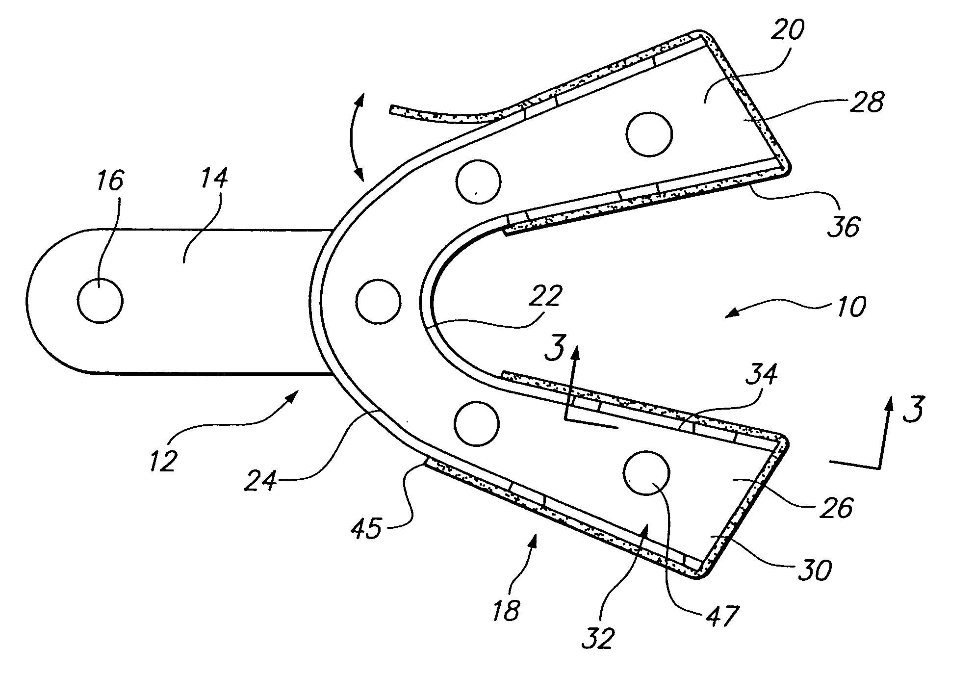
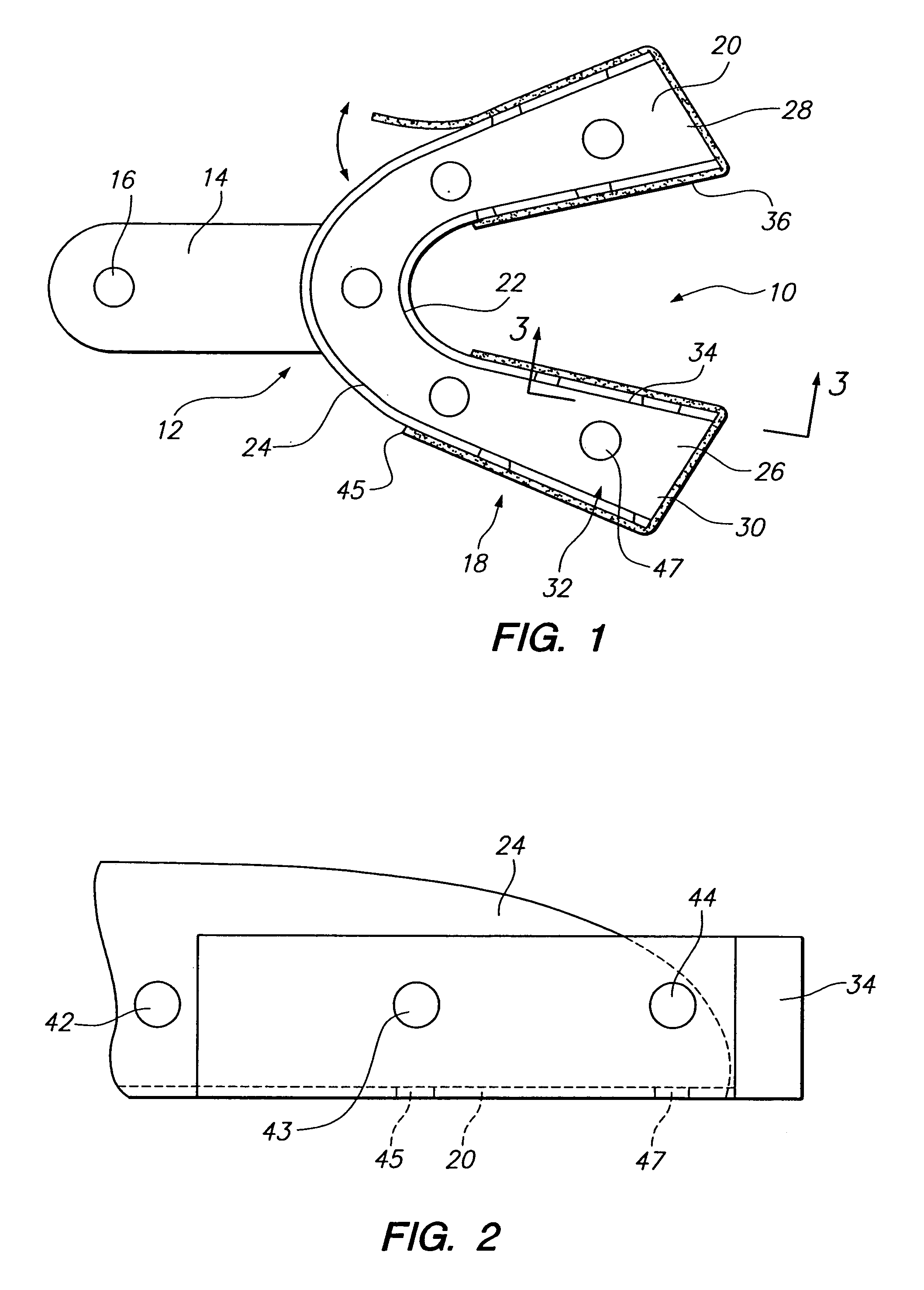
[0033]A preferred embodiment of the present invention is shown in its entirety in the drawings by reference character 10. System 10 possesses as one of its elements a tray member12, which is a lower jaw tray. It should be noted that the dam system of the present invention also applies to an upper jaw dental impression tray having a single end. Tray member 12 includes a handle 14 with a placement opening 16 therethrough. A cup or container section 18 is also depicted in FIG. 1. Container 18 is formed with a bottom 20 and outwardly extending wall portions 22 and 24. Bottom 20 and wall portions 22 and 24 form a basin 26 to hold dental impression material, which will be discussed hereinafter. It should be noted that ends 28 and 30 of basin 26 are open, lacking any seg...


PUM


Abstract

A dental impression dam system utilizing an open tray forming a basin for dental impression material. The basin of the tray includes a gap at an extremity of the same. A flexible band of material bridges the gap of the tray basin and interacts with the dental material to form unit. The band adheres to the external wall portions of the tray when in place.

Description


Claims


Application Information

Patent Timeline
Owner ROETZER PATRICK L
Why Eureka
Try Eureka