Tile measuring device

a technology for measuring devices and tiles, applied in the direction of circular curve drawing instruments, instruments, and mechanical means, etc., can solve the problems of increasing waste of time and materials, cutting tiles, and reducing efficiency

Active Publication Date: 2006-11-28
HUTTEMANN CHRISTOPHER
View PDF13 Cites 13 Cited by
  • Summary
  • Abstract
  • Description
  • Claims
  • Application Information

AI Technical Summary

Problems solved by technology

This typically results in a need to cut tiles, changing their dimensions for placement in specific areas such as at the edges of rooms and the like.
These devices are generally effective, but have a number of drawbacks that can reduce efficiency, increase wasted time and materials and cause a great deal of frustration.
Often overlooked, this error can result in miss-cut tiles and wasted time.
This prevents the use of many measuring devices.

Method used


Image

  • Tile measuring device
  • Tile measuring device
  • Tile measuring device

Examples


Embodiment Construction

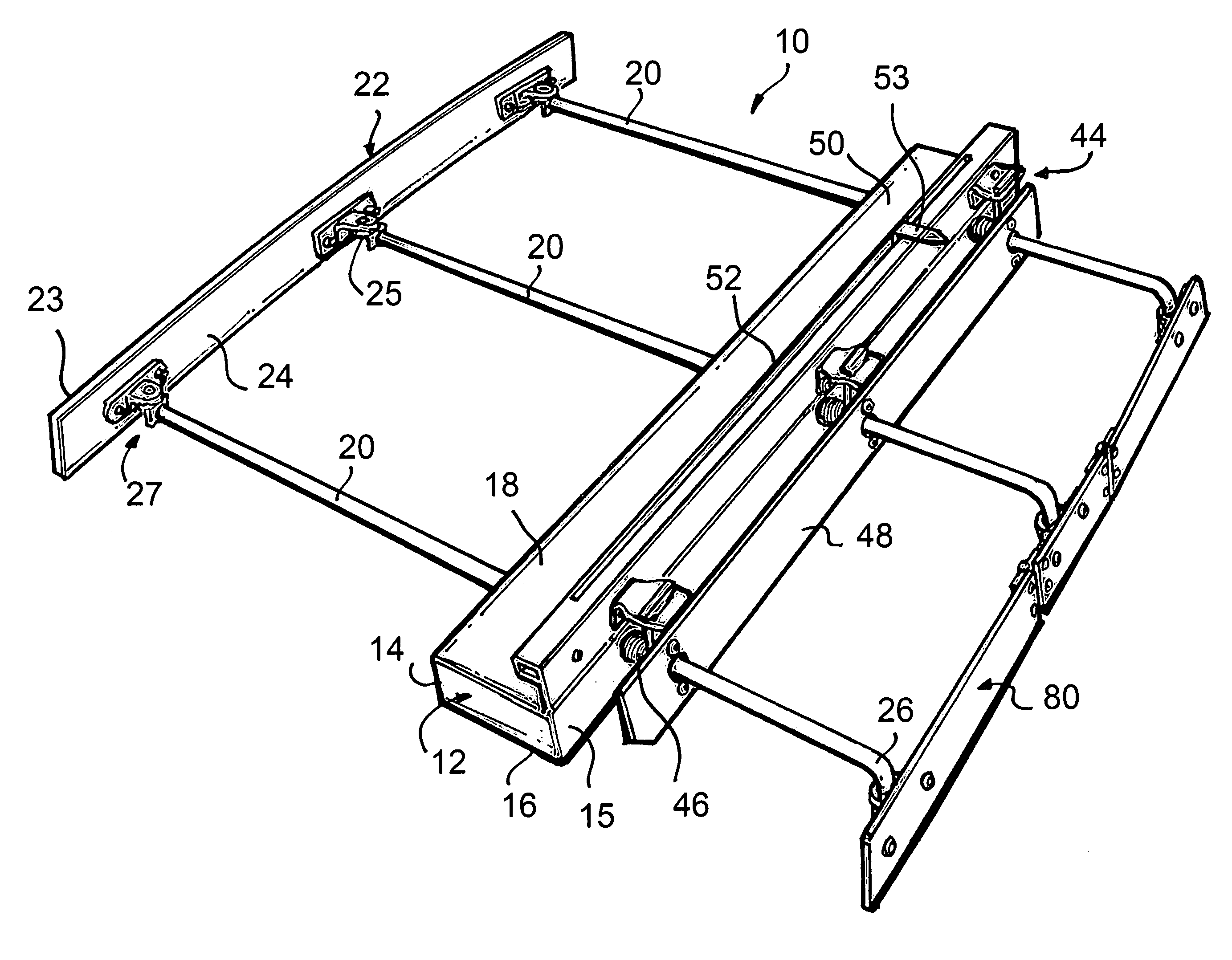
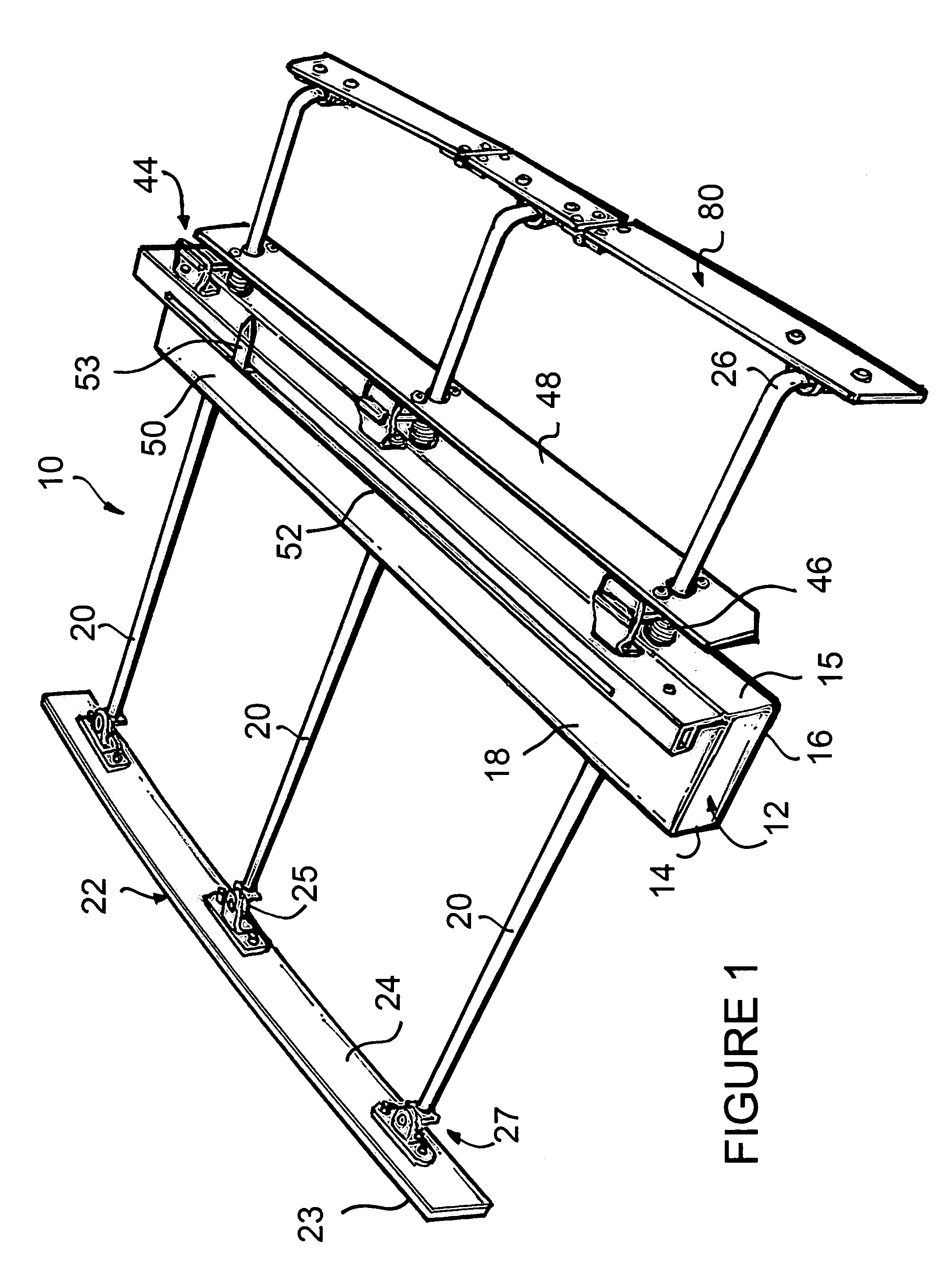
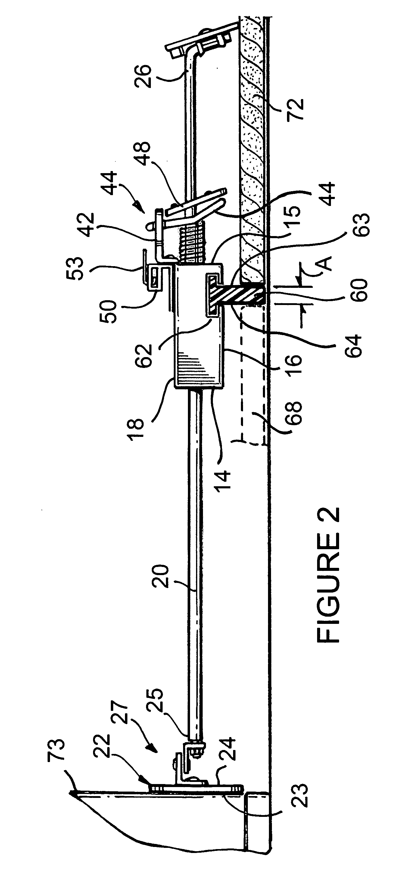
[0027]Turning now to the drawings in which like reference characters indicate corresponding elements throughout the several views, attention is first directed to FIGS. 1 and 2 which illustrate a tile measuring device generally designated 10. Tile measuring device 10 includes a reference bar member 12 having a front side 14, a rear side 15, a bottom side 16 and a top side 18. For purposes of orientation, the term front or forward is intended to indicate a direction toward an obstruction such as a wall against which a measurement is to be taken. Reference bar member 12 is an elongated member having a length sufficient to accommodate tiles of the desired size. It will be understood, that small tiles as well as large tiles can be measured with tile measuring device 10 using a reference bar member 12 of sufficient length to accommodate larger tiles. Accommodating smaller tiles on a measuring device 10 having any reference bar member 12 able to accommodate large tiles will be described pr...


PUM


Abstract

A tile measuring device includes a reference bar member having a bottom side with a gap gauge extending therefrom. A plurality of shafts extends through the reference bar member and terminating in a flexible contact bar conformable to an obstruction. Each shaft of the plurality of shafts is independently slidable through the reference bar member and held in position by a brake mechanism.

Description

FIELD OF THE INVENTION[0001]This invention relates to tools for the laying of tiles.[0002]More particularly, the present invention relates to devices for measuring tiles.BACKGROUND OF THE INVENTION[0003]It has long been appreciated, particularly by those skilled in the art of flooring installation, that careful measuring is required during the installation of tiles. While tiles are of fixed dimensions and shape, the surfaces upon which they are laid very seldom are. This typically results in a need to cut tiles, changing their dimensions for placement in specific areas such as at the edges of rooms and the like. There are a multitude of devices employed for measuring tiles to be cut. These operate in almost as many different ways as there are devices. Typically, these devices permit a distance to be measured from the edge of a laid tile to a wall or other obstruction. This measurement can then be employed to cut a tile to fit. These devices are generally effective, but have a number...

Claims


Application Information

Patent Timeline
Patent Type & Authority Patents(United States)
IPC IPC(8): G01B5/20
CPCG01B3/30E04F21/0076
Inventor HUTTEMANN, CHRISTOPHER
Owner HUTTEMANN CHRISTOPHER
Why Eureka
Try Eureka