CMP conditioner

a conditioner and conditioner technology, applied in the direction of gear teeth, gear teeth, gear-teeth manufacturing apparatus, etc., can solve the problems of unavoidable scratching, inability to be sure, scratching will be generated on the surface being polished, etc., to prevent diamond grit from falling off

Active Publication Date: 2006-12-19
MITSUBISHI MATERIALS CORP
View PDF5 Cites 39 Cited by
  • Summary
  • Abstract
  • Description
  • Claims
  • Application Information

AI Technical Summary

Benefits of technology

[0009]The present invention was conceived in view of these circumstances and it is an object thereof to provide a CMP conditioner that prevents any large-scale reduction early on in the polishing rate in a CMP conditioner that is used in the conditioning for polishing pads of the aforementioned CMP apparatus, and that reliably prevents scratches from occurring in a polished surface such as a semiconductor wafer that is being polished by the CMP apparatus, and that enables stable conditioning to be performed over an extended period of time for polishing pads that are capable of forming a high-quality polished surface.
[0011]Accordingly, in this type of CMP conditioner, diamond grit is adhered to a conditioning surface such that 111 surface of the crystal surfaces of the diamond grit is made substantially parallel with the conditioning surface and is made to face in the direction faced by the conditioning surface, namely, are made to face in a direction facing a polishing pad in the CMP apparatus. Because these 111 surfaces form protruding end surfaces that protrude from the conditioning surface and are in contact with the polishing pad, sharp portions such as ridge line portions and peak portions between crystal surfaces of the diamond grit do not form protruding ends that protrude towards the polishing pad side. As a result, it is possible to prevent any marked deterioration in the polishing rate that is caused by these sharp portions wearing out at an early stage, and it is possible to prevent breakages occurring in these portions and to thereby prevent the broken fragments from causing scratches in a surface being polished of a semiconductor wafer or the like that is being polished by a polishing pad.
[0012]In addition, because it is the ridge line portions and peak portions between 111 surfaces, which are extremely strong and wear resistant and form the aforementioned protruding end surfaces, and other crystal surfaces, which are adjacent to the 111 surfaces, of the diamond grit that act as cutting blades and are cut into the polishing pads, and because the 111 surfaces that form protruding end surfaces remain in a state of constantly facing and being in contact with the polishing pad even if the grinding direction of the diamond grit as it grinds the polishing pad changes, the cutting blades are able to maintain excellent cutting quality, and there is little wear. Moreover, there are no broken fragments. Accordingly, according to a CMP conditioner having this structure, a high polishing rate can be consistently maintained over an extended period, and a lengthening of the conditioner lifespan can be achieved. In addition, in a semiconductor wafer that is polished by a polishing pad that has been conditioned using this conditioner, a high quality polished surface that is unscratched can be formed.
[0014]Therefore, based on this understanding, in the CMP conditioner of the present invention, on the above described conditioning surface, it is desirable that the 111 surface detection ratio when an X-ray diffraction intensity of crystal surfaces of the diamond grit is measured at a plurality of measurement positions on the conditioning surface averages 70% or more at the plurality of measurement positions. By having this type of high 111 surface detection ratio, the aforementioned effects can be more reliably exhibited. Namely, if this 111 surface detection ratio is less than 70%, then the proportion of diamond grains that are adhered with other crystal surfaces acting as protruding end surfaces, and the proportion of diamond grit that is adhered with protruding ridge lines and peak portions between adjacent crystal surfaces become relatively greater. Consequently, the concerns arise that the polishing rate will be made to deteriorate markedly at an early stage as a result of these grits, or that the possibility of scratches occurring will be increased because of breakages.
[0016]Furthermore, particularly in a CMP conditioner in which diamond grit is adhered using a plating phase of a metal such as nickel, as is the case in the patent document 1, or in a CMP conditioner in which diamond grit is adhered by brazing using a metal brazing material, as is the case in the patent document 2, it is desirable that a tetrafluoride organic compound be coated onto the conditioning surface in order to prevent the occurrence of scratches that are caused by pieces of grit dropping off due to corrosion of the metal bonding phase in which the diamond grit is adhered even when a highly corrosive slurry is used when conditioning a polishing pad in a CMP apparatus. Namely, because this type of tetrafluoride organic compound is extremely corrosion resistant due to no —CONH2, —CH2OH, —COOCH8, —COF, —COOH, and —CCF2H and the like, which easily react with highly corrosive slurries, being present therein, and because the metal bonding phase can also be reliably covered by an electropainting or the like, it is possible to more effectively prevent the diamond grit from falling off due to such corrosion of the metal bonding phase, and to prevent the occurrence of scratches that are the result of such falling grit.

Problems solved by technology

Moreover, if the ridge portions and, in particular, the peak portions of the crystals form protruding ends in this manner, as is described above, these portions end up being lost before they are worn out so that there is a possibility that the chipped fragments thereof will scratch the surface being polished of the semiconductor wafer or the like that is being polished by a CMP apparatus, and that scratches will be generated in the surface that is being polished.
As a result, it is not always certain that the projection lines of the vertical lines of the {111} surface of the grit that has been brazed to the conditioning surface will be parallel to the grinding direction.
In addition, chipped fragments occur in these ridge lines and peak portions and the occurrence of scratching is unavoidable.

Method used


Image

  • CMP conditioner
  • CMP conditioner
  • CMP conditioner

Examples


examples

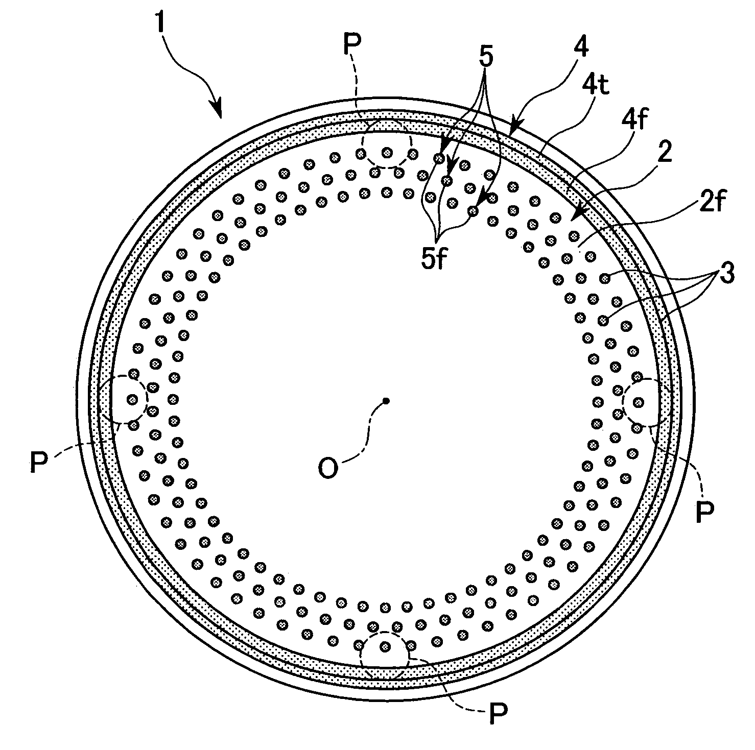
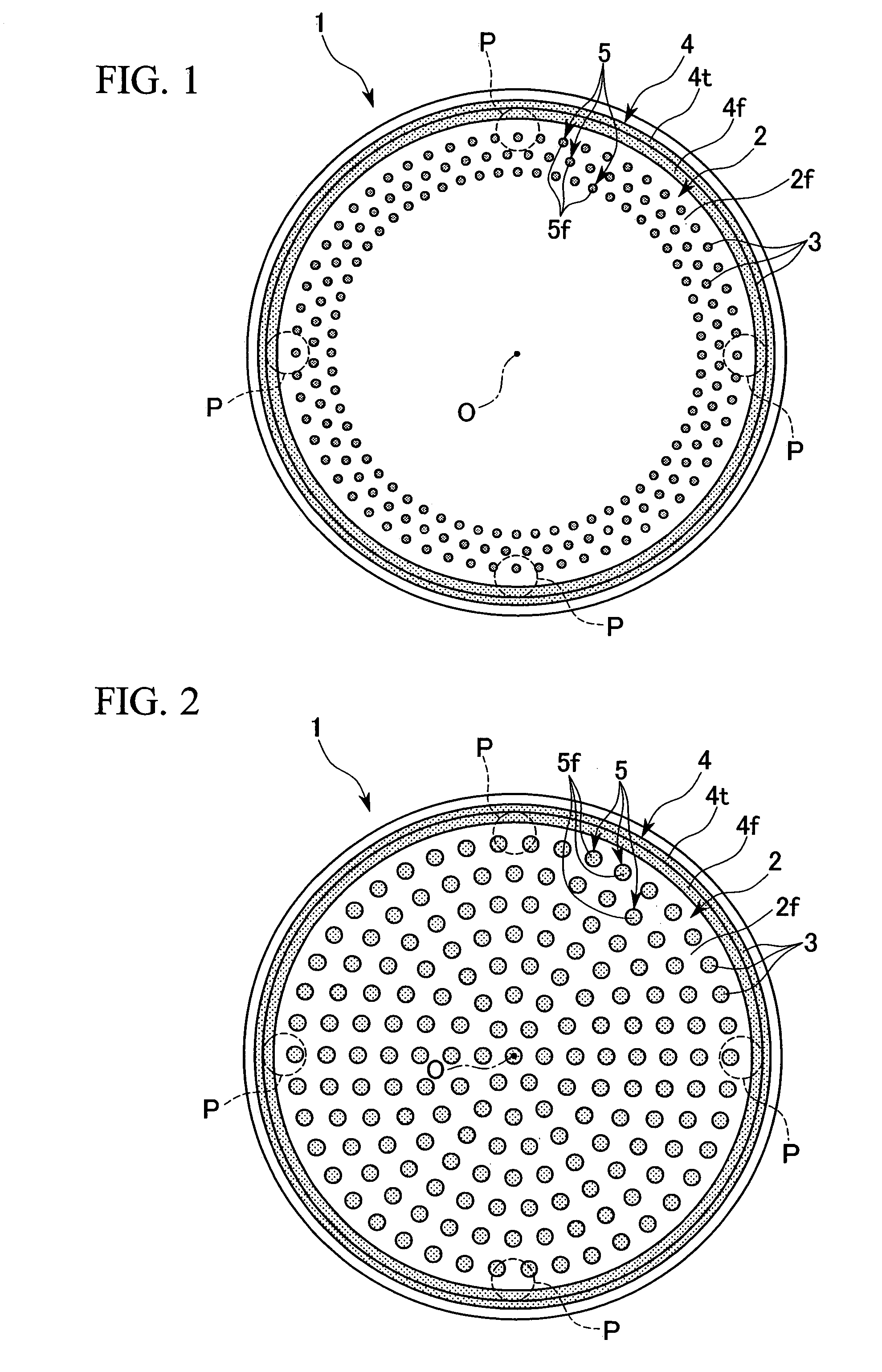
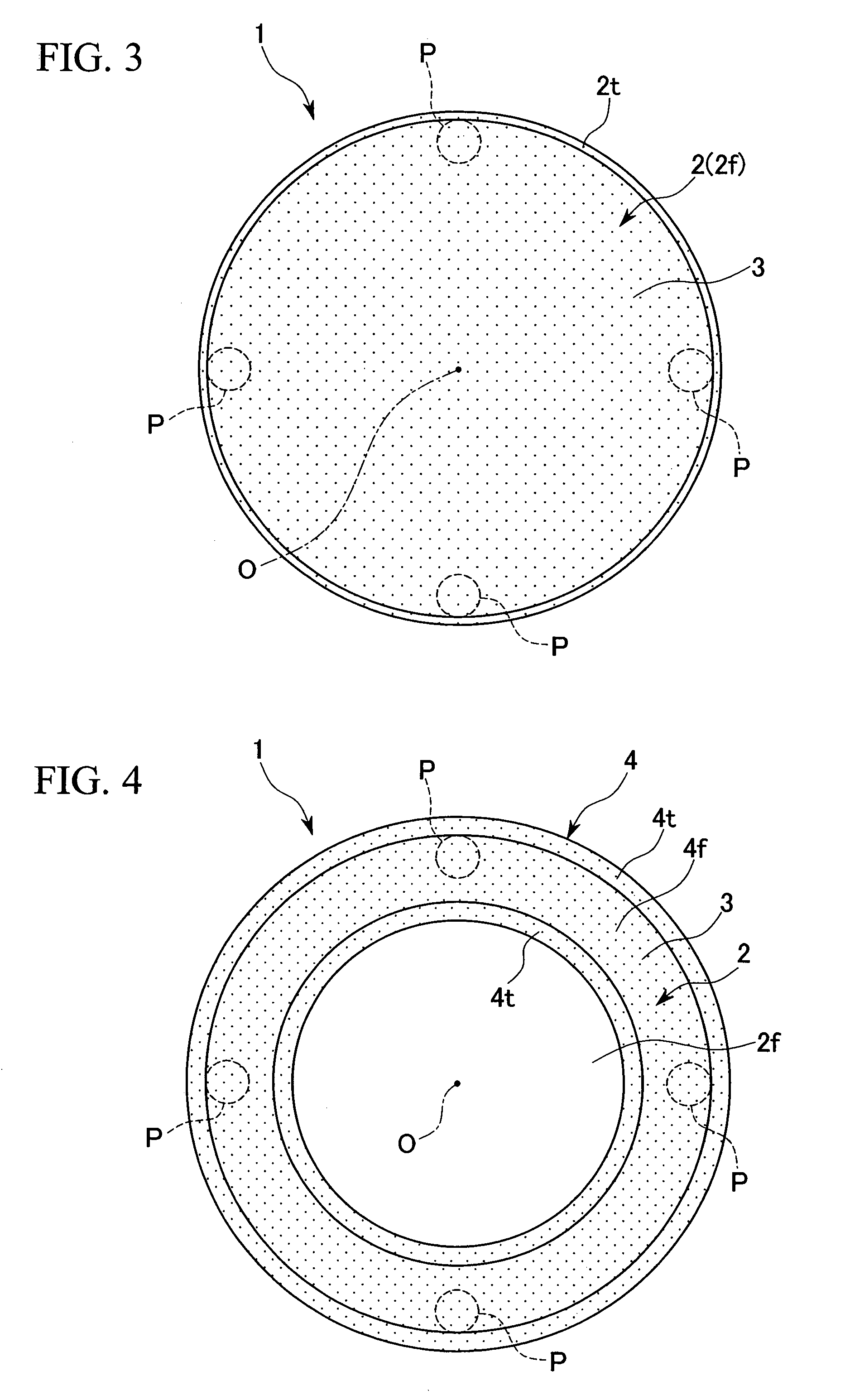
[0032]Next, the effects of the present invention will be demonstrated by giving examples of the present invention based on the above embodiments. In these examples, firstly, three types of CMP conditioner were manufactured by altering the particle size of the diamond grit based on the first embodiment, and two types of CMP conditioner were manufactured by altering the particle size of the diamond grit based on the second embodiment. These made up Examples 1 to 5. Examples 1 to 3 are based on the first embodiment and the particle size of the diamond grit was #100 in Example 1, #200 in Example 2, and #325 in Example 3. Examples 4 and 5 are based on the second embodiment and the particle size of the diamond grit was #100 in Example 4 and #325 in Example 5. The grit concentration was the number of pieces of diamond grit adhering per unit area (1 mm2) in the grit layer 3 and was an average of 35 pieces of grit / mm2 for a particle size of #100 (i.e., Examples 1 and 4), an average of 135 pi...


PUM


Abstract

A CMP conditioner is provided in which diamond grit that is adhered to a conditioning surface so as to face and be in contact with a polishing pad of a CMP apparatus is adhered such that 111 surfaces of crystal surfaces of the diamond grit are substantially parallel with the conditioning surface and face in a direction faced by the conditioning surface.

Description

BACKGROUND OF THE INVENTION[0001]1. Field of the Invention[0002]The present invention relates to a CMP conditioner that is used in the conditioning of polishing pads of a chemical mechanical polishing (CMP) apparatus that polishes semiconductor wafers and the like.[0003]Priority is claimed on Japanese Patent Application No. 2004-274912, filed Sep. 22, 2004, the contents of which are incorporated herein by reference.[0004]2. Description of Related Art[0005]For this type of CMP conditioner, a technology has been proposed, for example, in patent document 1 (Japanese Unexamined Patent Application, First Publication No. 2001-71267) in which, in a pad conditioning diamond dresser in which a single layer of diamond grit is adhered to a base metal operating surface of a disk-shaped or cup-shaped base metal by nickel plating, 70% or more of the adhered diamond grit has ridges or peaks of crystals as protruding ends. Moreover, in patent document 2 (Japanese Unexamined Patent Application, Firs...

Claims


Application Information

Patent Timeline
Patent Type & Authority Patents(United States)
IPC IPC(8): B24B21/18
CPCB24B53/017B24B53/12
Inventor YAMASHITA, TETSUJIKIMURA, TAKASHIHATA, HANAKO
Owner MITSUBISHI MATERIALS CORP
Why Eureka
Try Eureka