
Multi-nozzle assembly for extrusion of wall

a multi-nozzle, wall technology, applied in the direction of rigid containers, pliable tubular containers, packaging, etc., can solve the problems of difficult and difficult construction, difficult and difficult problems, and difficulty in efficient use of time of many individuals

Active Publication Date: 2006-12-26
UNIV OF SOUTHERN CALIFORNIA
View PDF19 Cites 92 Cited by
  • Summary
  • Abstract
  • Description
  • Claims
  • Application Information

AI Technical Summary

Benefits of technology

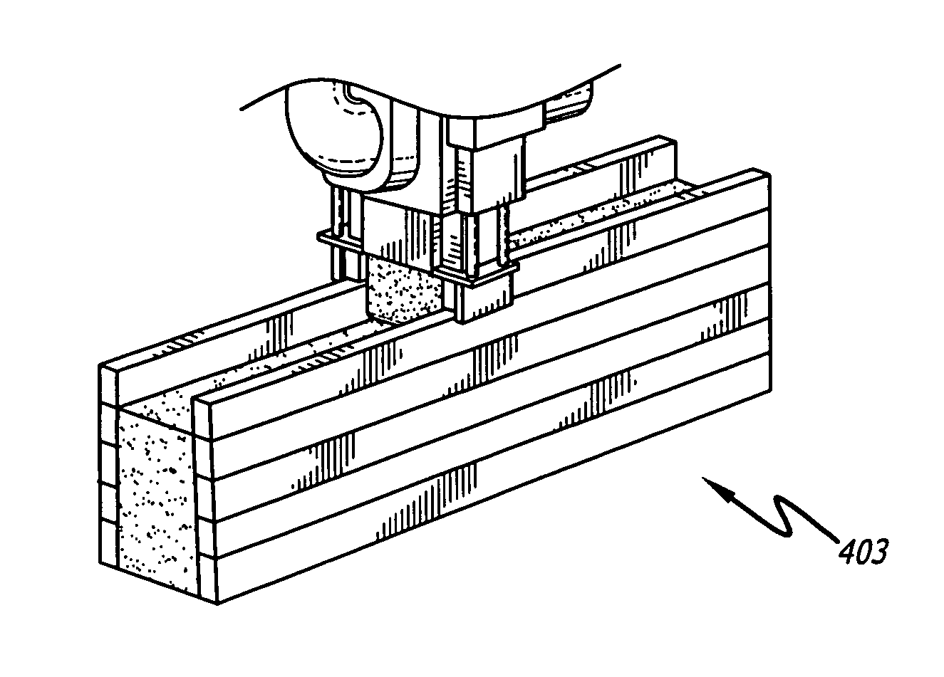
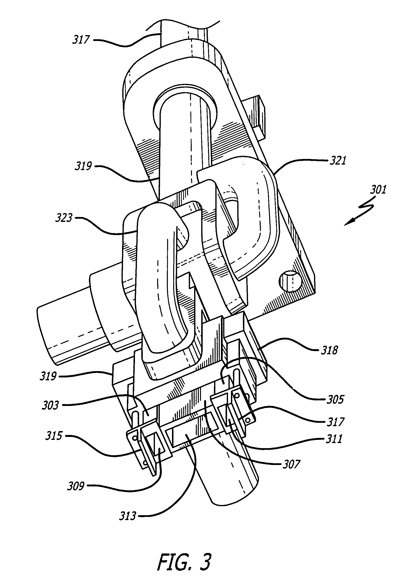
The patent describes a multi-nozzle assembly for extruding material. The assembly includes three nozzles that can extrude material through different outlets. The outlets have a rectangular cross-section and can be controlled in height. The assembly also includes a trowel to shape the material extruded from the nozzles. The width of the outlets can be different, and the assembly can be controlled in three dimensions. The assembly can be mounted on a gantry robot or other motion control platform. The assembly also includes a material feed system to keep the material separate from each other and a controllable gate to block the flow of material. The patent also describes a construction method where two layers of rims and filler can be simultaneously extruded and cured. The rims and filler can be made of different materials, and the rims can have different levels within the wall. The technical effects of the patent include improved precision and control in extruding material and improved strength and durability of the resulting structures.

Problems solved by technology

Despite all of the centuries of development, however, there can be difficulties and problems.
Construction is usually very labor intensive.
This can be very costly.
Simultaneously using the time of numerous individuals in an efficient manner can also be challenging.
The results of the construction effort can also be inconsistent.
This can be caused by differences in the skills, efforts, supervision and techniques employed by those that work on the structures.
Construction may also result in wasted material.
For example, when wood is used, standard, off-the-shelf lengths must often be cut to meet design requirements, resulting in waste.
Construction using manual labor can also be very time-consuming, requiring months and, in some instances, years to complete.
Construction can also be hazardous.
Many construction workers are killed or seriously injured at construction sites, including about 500,000 in the United States alone.

Method used


Image

  • Multi-nozzle assembly for extrusion of wall
  • Multi-nozzle assembly for extrusion of wall
  • Multi-nozzle assembly for extrusion of wall

Examples


Embodiment Construction

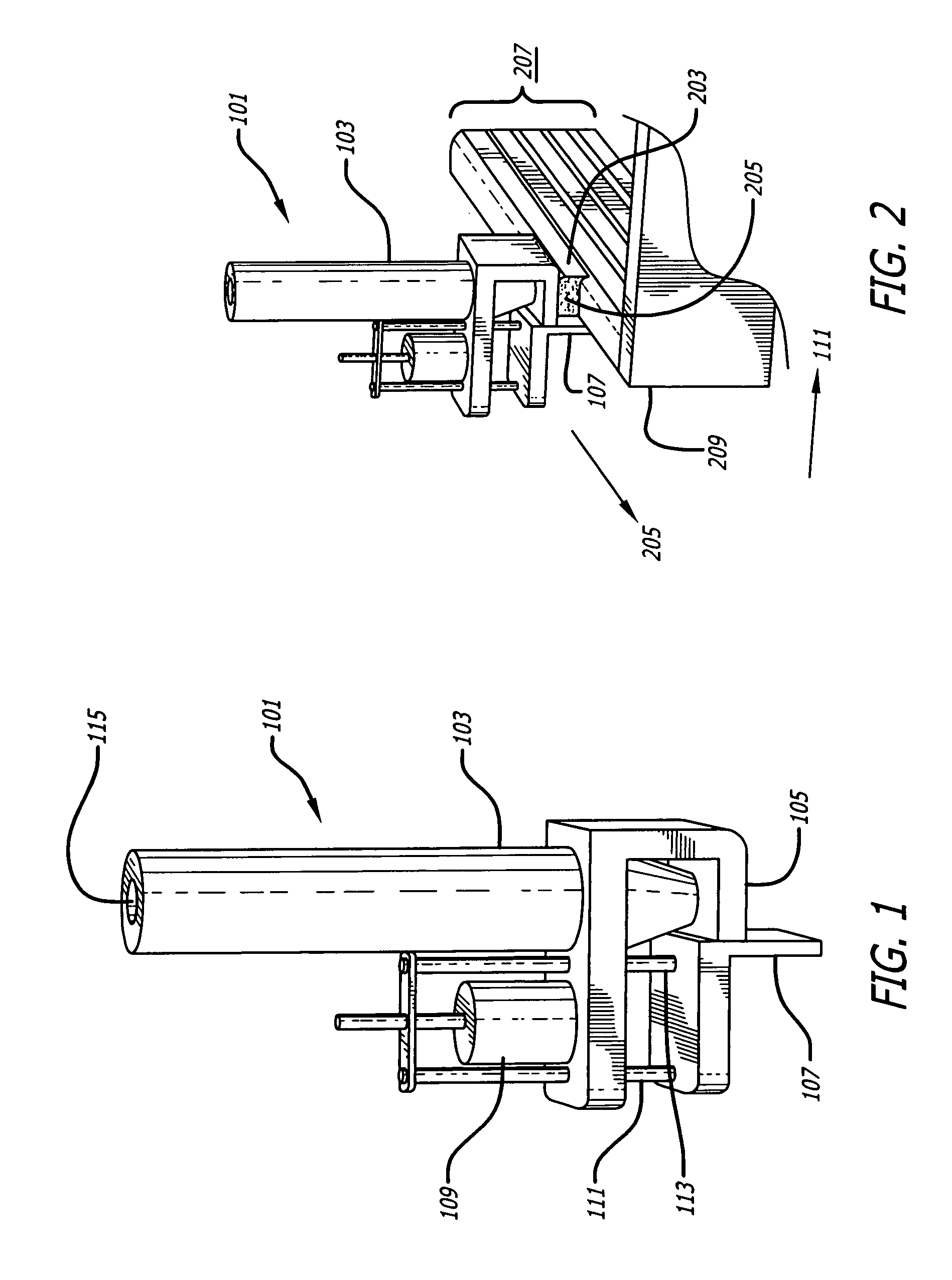
[0048]FIG. 1 illustrates an embodiment of a nozzle assembly that includes a single nozzle. As shown in FIG. 1, a nozzle assembly 101 may include a nozzle 103 having an outlet 105 (not visible in FIG. 1), a trowel 107, and a trowel positioning controller, including a servo motor 109 and trowel linkage 111 and 113.

[0049]Although shown as cylindrical, the shape of the nozzle 103 may vary. It may include an inlet 115 for material in a fluid or semi-fluid form.

[0050]The cross-section of the outlet 105 may vary. It may be circular, rectangular or of some other shape.

[0051]FIG. 2 illustrates the embodiment of the nozzle assembly shown in FIG. 1 being used to extrude a wall. As shown in FIG. 2, the nozzle assembly 101 is extruding a layer of material 203 while being moved in a horizontal direction 205. The trowel 107 smoothens the exterior surface of the layer of material 203 as it is being extruded from the nozzle 103. The lower surface 205 of the member that supports the nozzle 103 has an...


PUM

PropertyMeasurementUnit
anglesaaaaaaaaaa
heightaaaaaaaaaa
widthaaaaaaaaaa

Abstract

A multi-nozzle assembly may include a first nozzle configured to extrude material through a first outlet; a second nozzle configured to extrude material through a second outlet; and a third nozzle configured to extrude material through a third outlet, the third outlet being between the first and second outlets. Related construction processes and wall structures are also disclosed.

Description

CROSS-REFERENCE TO RELATED APPLICATIONS[0001]This application is based upon and claims priority to U.S. Provisional Application Ser. No. 60 / 441,572, entitled “Automated Construction,” filed on Jan. 21, 2003, by inventor Behrokh Khoshnevis, This application is also based upon U.S. Provisional Application Ser. No. 60 / 537,756, filed Jan. 20, 2004, entitled. “Automated Construction Techniques,” filed concurrently with this application, also by inventor Behrokh Khoshnevis. The entire content of both of these provisional applications is incorporated herein by reference.GOVERNMENT'S INTEREST IN APPLICATION[0002]This invention was made with government support under NSF Grant No. 9634962 and NSF Grant No. 9522982 awarded by the United States Government. The government has certain rights in the invention.BACKGROUND[0003]1. Field[0004]This application relates to the construction of structures, including the construction of walls and roofs. This application also relates to the extrusion of mate...

Claims


Application Information

Patent Timeline
Patent Type & Authority Patents(United States)
IPC IPC(8): B29C47/00B29C47/02B29C47/06B29C47/60B29C67/00B65D35/28B65D35/34E04BE04B1/16E04B2/02E04G11/06
CPCB29C67/0055B28B1/001E04G2021/049E04G21/0463B29C64/118B29C64/106B33Y30/00E04G11/34
Inventor KHOSHNEVIS, BEHROKH
Owner UNIV OF SOUTHERN CALIFORNIA
Learn More