
State retention power gating latch circuit

a technology of state retention and latch circuit, which is applied in the field of electromechanical devices, can solve the problems of significant static leakage current in the powered down state, and achieve the effect of reducing the number of static leakage currents

Active Publication Date: 2007-01-16
NXP USA INC
View PDF7 Cites 31 Cited by
  • Summary
  • Abstract
  • Description
  • Claims
  • Application Information

AI Technical Summary

Problems solved by technology

The state saving latches remain powered and thus consume a significant amount of static leakage current in the powered down state.

Method used


Image

  • State retention power gating latch circuit
  • State retention power gating latch circuit
  • State retention power gating latch circuit

Examples


Embodiment Construction

[0012]The following description is presented to enable one of ordinary skill in the art to make and use the present invention as provided within the context of a particular application and its requirements. Various modifications to the preferred embodiment will, however, be apparent to one skilled in the art, and the general principles defined herein may be applied to other embodiments. Therefore, the present invention is not intended to be limited to the particular embodiments shown and described herein, but is to be accorded the widest scope consistent with the principles and novel features herein disclosed.

[0013]The terms “a” or “an”, as used herein, are defined as one or more than one. The term “plurality”, as used herein, is defined as two or more. The term “another”, as used herein, is defined as at least a second or more. The terms “including” and / or “having”, as used herein, are defined as comprising (i.e., open language). The term “coupled”, as used herein, is defined as co...


PUM


Abstract

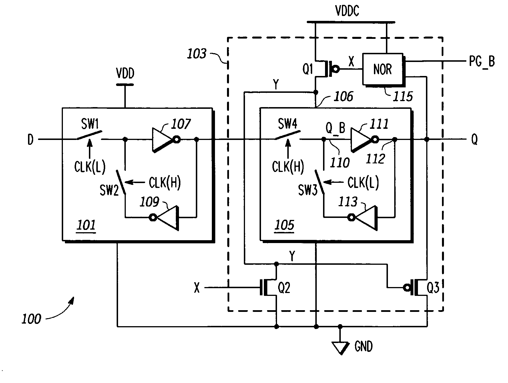
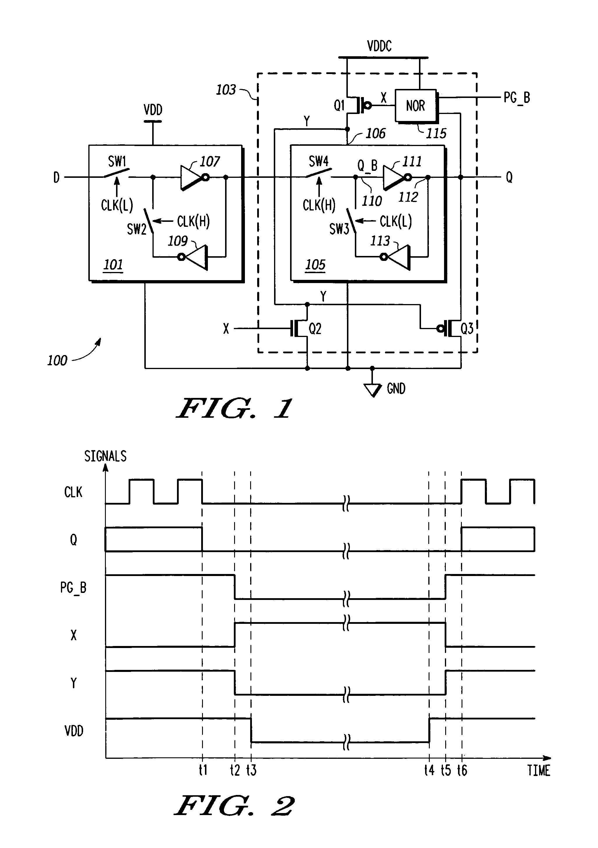
A method of power gating a latch including detecting a state of the latch, detecting a power gate signal, providing power to the latch while the power gate signal is negated, and removing power from the latch when the power gate signal is asserted and the latch is in a predetermined state. The method may include any one or more of pulling a node of the latch to a selected state while the power gate signal is asserted to ensure that the latch powers up in the predetermined state, providing a signal indicative of the latch state and the power gate signal to respective inputs of a logic gate having an output indicative thereof, switching a supply voltage to a power input of the latch based on a state of the output of the logic gate, and closing a switch to pull a node of the latch low.

Description

BACKGROUND OF THE INVENTION[0001]1. Field of the Invention[0002]The present invention relates in general to electronic devices, and more particularly to an imbalanced state retention power gating (SRPG) latch circuit that forces a known state upon power-up depending upon the state being stored to save additional static leakage current.[0003]2. Description of the Related Art[0004]State retention power gating (SRPG) is a way to save static leakage current by powering down a majority of a synchronous digital logic block while maintaining power on the flip flops where the state of the digital logic is saved. Various forms of SRPG flip flops have been disclosed and described. The conventional SRPG configurations were implemented according to an assumption, however, that either state (“0” or “1”) of the flip flop must be saved since it is unknown which state is required to be saved at any given time. The present disclosure challenges this assumption. A common flip flop configuration is a ...

Claims


Application Information

Patent Timeline
Patent Type & Authority Patents(United States)
IPC IPC(8): H03K3/289H03K3/356
CPCH03K3/356008H03K3/012
Inventor CHUN, CHRISTOPHER K. Y.
Owner NXP USA INC
Learn More