Segmented flexible barrel lay-up mandrel

a flexible, segmented technology, applied in the direction of dough shaping, manufacturing tools, food shaping, etc., can solve the problems of large handling equipment, significant challenges in the fabrication of components with complex shapes, and large rigid segments that cannot be disassembled, so as to improve the removal procedure of composite components and improve the sealing characteristics

Inactive Publication Date: 2007-01-23
THE BOEING CO
View PDF41 Cites 42 Cited by
  • Summary
  • Abstract
  • Description
  • Claims
  • Application Information

AI Technical Summary

Benefits of technology

[0006]It is therefore an object to the present invention to provide an aircraft barrel lay-up assembly with improved composite component removal procedures. It is further object of the present invention to provide an aircraft barrel lay-up assembly with improved joint sealing characteristics.

Problems solved by technology

Although this procedure is well known and understood, it can generate significant challenges for the fabrication of components with complex shapes.
Aircraft dimensional proportions, however, dictate that these rigid segments become heavy and commonly require large handling equipment to disassemble.
This is highly undesirable as a host of time consuming and hazardous procedures must be implemented.
Present mandrel configurations, therefore, contribute negatively to the production flow timing.
In addition, the multiple rigid segments utilized in present designs result in a plurality of joints, each of which representing a potential source of vacuum leaking.
Vacuum leaks can result in defects in the laminate and possible scraping of the resultant part.

Method used


Image

  • Segmented flexible barrel lay-up mandrel
  • Segmented flexible barrel lay-up mandrel
  • Segmented flexible barrel lay-up mandrel

Examples


Embodiment Construction

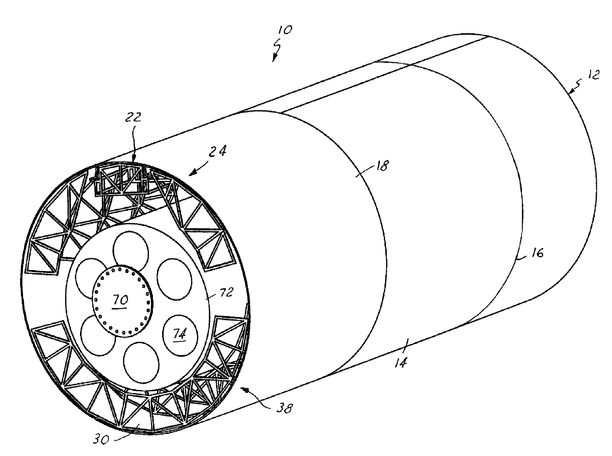
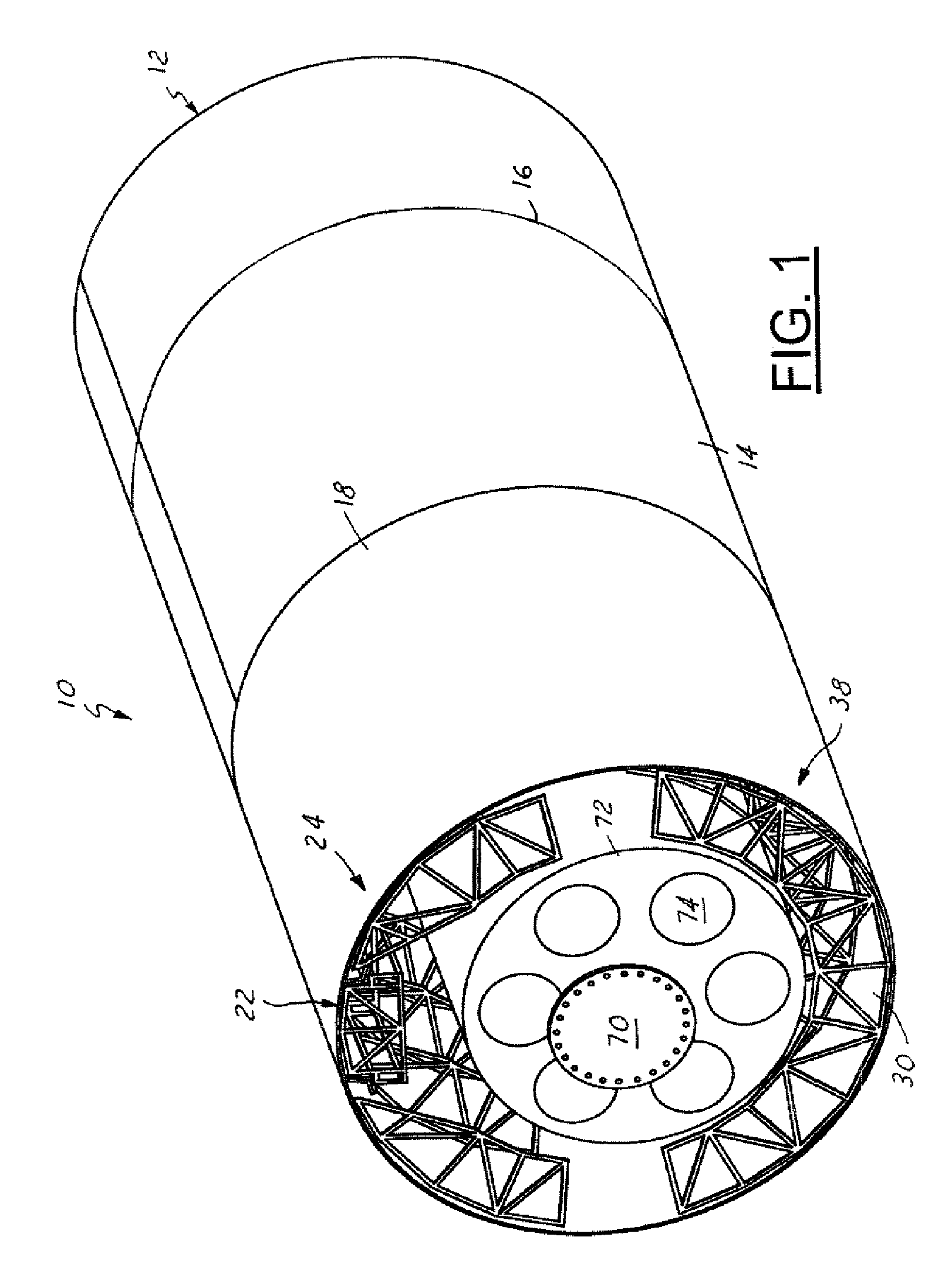
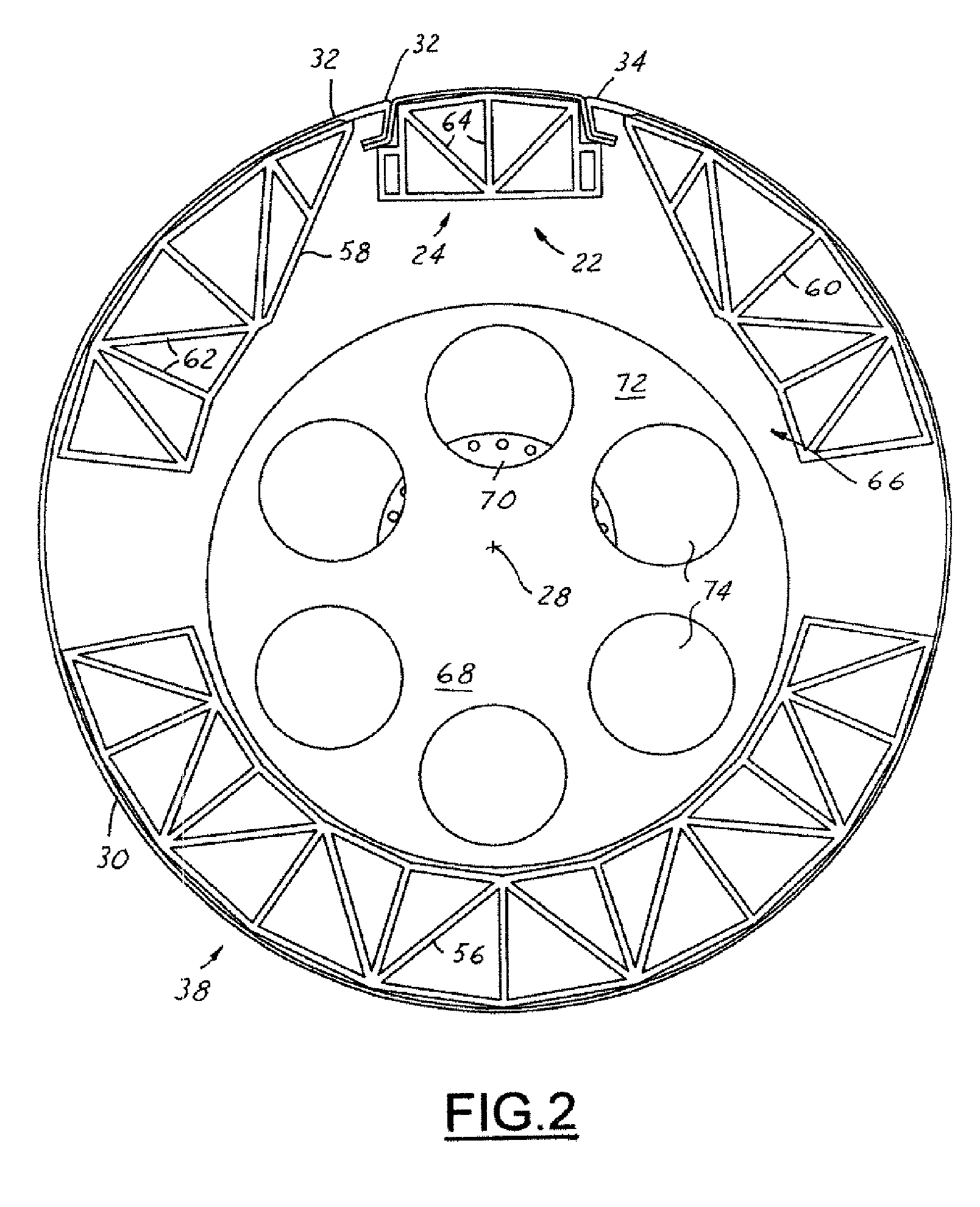
[0016]Referring now to FIGS. 1 through 3, which are illustrations of an aircraft barrel lay-up assembly 10 in accordance with the present invention. The barrel lay-up assembly 10 includes a barrel mandrel assembly 12 with a contiguous outer barrel lay up surface 14 having a barrel mandrel circumference 16. A composite ply assembly 18 is laid up onto the contiguous outer barrel lay-up surface 14 and cured to generate a composite barrel element 20. The present invention provides a unique apparatus and method to generate the contiguous outer barrel lay-up surface 14 and remove the composite barrel element 20 from the barrel mandrel assembly 12.

[0017]The barrel mandrel assembly 12 is actually comprised of a minor barrel outer surface element 22 representing approximately 20 percent of the barrel mandrel circumference 16 or an otherwise minority portion. The minor barrel outer surface element 22 is movable between a minor barrel engaged position 24 and a minor barrel disengaged position ...


PUM

PropertyMeasurementUnit
circumferenceaaaaaaaaaa
forceaaaaaaaaaa
shapesaaaaaaaaaa

Abstract

An aircraft barrel lay-up assembly is provided comprising a barrel mandrel assembly having a contiguous outer barrel lay-up surface. A minor barrel outer surface element is movable between a minor barrel engaged position and a minor barrel disengaged position and forms a minority portion of the contiguous outer barrel lay-up surface when in the engaged position. A major barrel outer surface element is movable between a major barrel engaged position and a major barrel disengaged position. The major barrel outer surface has a first major barrel surface end and a second major barrel surface end moving together to reduce an effective major barrel outer surface circumference when in the major barrel disengaged position. A composite ply assembly is formed around the barrel mandrel circumference and cured while coincident to form a composite barrel element. The composite barrel element removable from said barrel mandrel assembly by way of moving major barrel outer surface element into the major barrel disengaged position such that a sliding gap is formed.

Description

TECHNICAL FIELD[0001]The present invention relates generally to an aircraft barrel lay-up mandrel assembly and more particularly to an aircraft barrel lay-up assembly with improved composite ply removal features.BACKGROUND OF THE INVENTION[0002]Aircraft components and structural members come in a wide variety of complex shapes and sizes. Weight and strength considerations have led to construction technologies such as composite ply lay-up methodologies. In such methodologies, epoxy infused materials are layed up onto mandrels or similar structures and then subjected to curing procedures. Once cured, the composite plies are then removed. Although this procedure is well known and understood, it can generate significant challenges for the fabrication of components with complex shapes.[0003]Such is the case with barrel shaped components. Components such as fuselage skins and stringers must commonly be laid up on complex mandrels composed of multiple rigid segments prior to curing. Once c...

Claims


Application Information

Patent Timeline
Patent Type & Authority Patents(United States)
IPC IPC(8): B29C70/44
CPCB29C70/32B29L2031/3082B64F5/10
Inventor BLANKINSHIP, BRUCE C.
Owner THE BOEING CO
Why Eureka
Try Eureka