Method and apparatus for creating a groove in a collector ring of an electrical device

a collector ring and groove technology, applied in the direction of grinding drives, generators/motors, grinding drives, etc., can solve the problems of reducing affecting the service life of the collector ring,

Inactive Publication Date: 2007-01-30
CUTSFORTH PRODS
View PDF20 Cites 4 Cited by
  • Summary
  • Abstract
  • Description
  • Claims
  • Application Information

AI Technical Summary

Problems solved by technology

For example, the grooves help to reduce selective action of the brushes, which can cause catastrophic failure of the brush to ring contacts.
For example, if the collector ring goes out of round, and needs to be re-trued, the re-truing operation can wear away the groove.
However, many of the known processes for initially creating such grooves, or for re-forming or enhancing such grooves are difficult to perform or are very time consuming.

Method used


Image

  • Method and apparatus for creating a groove in a collector ring of an electrical device
  • Method and apparatus for creating a groove in a collector ring of an electrical device
  • Method and apparatus for creating a groove in a collector ring of an electrical device

Examples


Embodiment Construction

[0013]The following detailed description should be read with reference to the figures, in which like elements in different figures are numbered in like fashion. The figures, which are not necessarily to scale, depict selected embodiments and are not intended to limit the scope of the invention. In some cases, the figures may be highly diagrammatic in nature. Examples of constructions, materials, dimensions, and manufacturing processes are provided for various elements. Those skilled in the art will recognize that many of the examples provided have suitable alternatives that may be utilized.

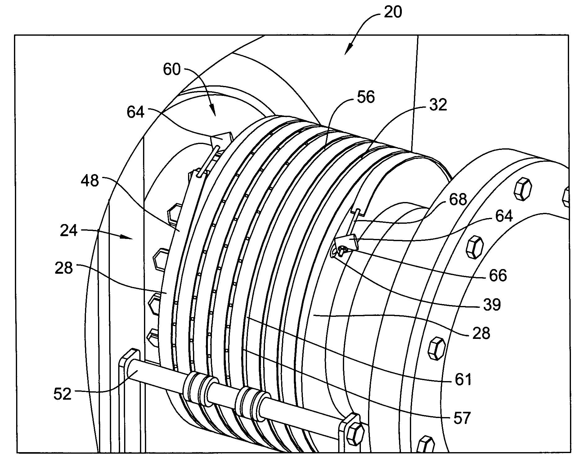
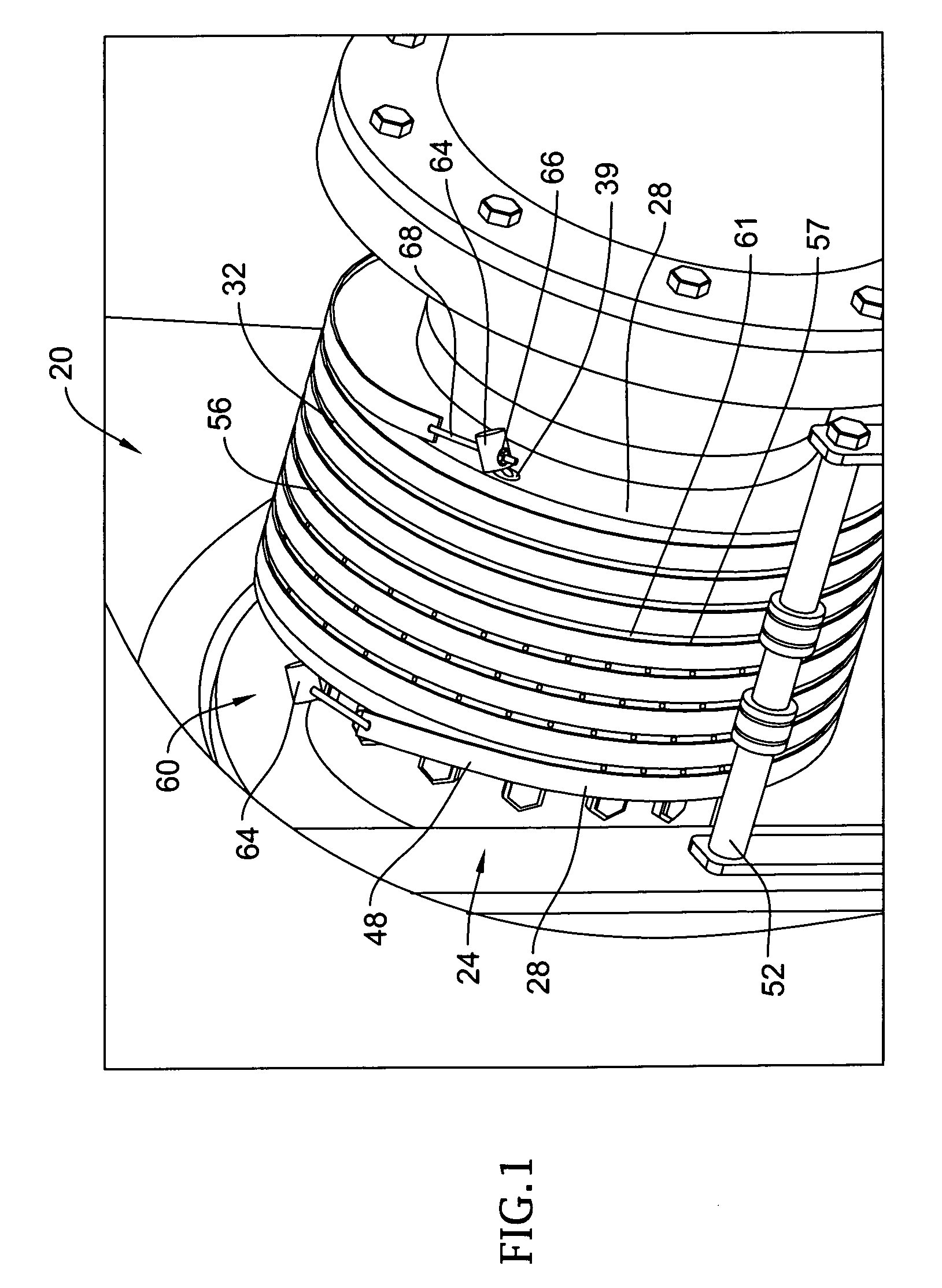
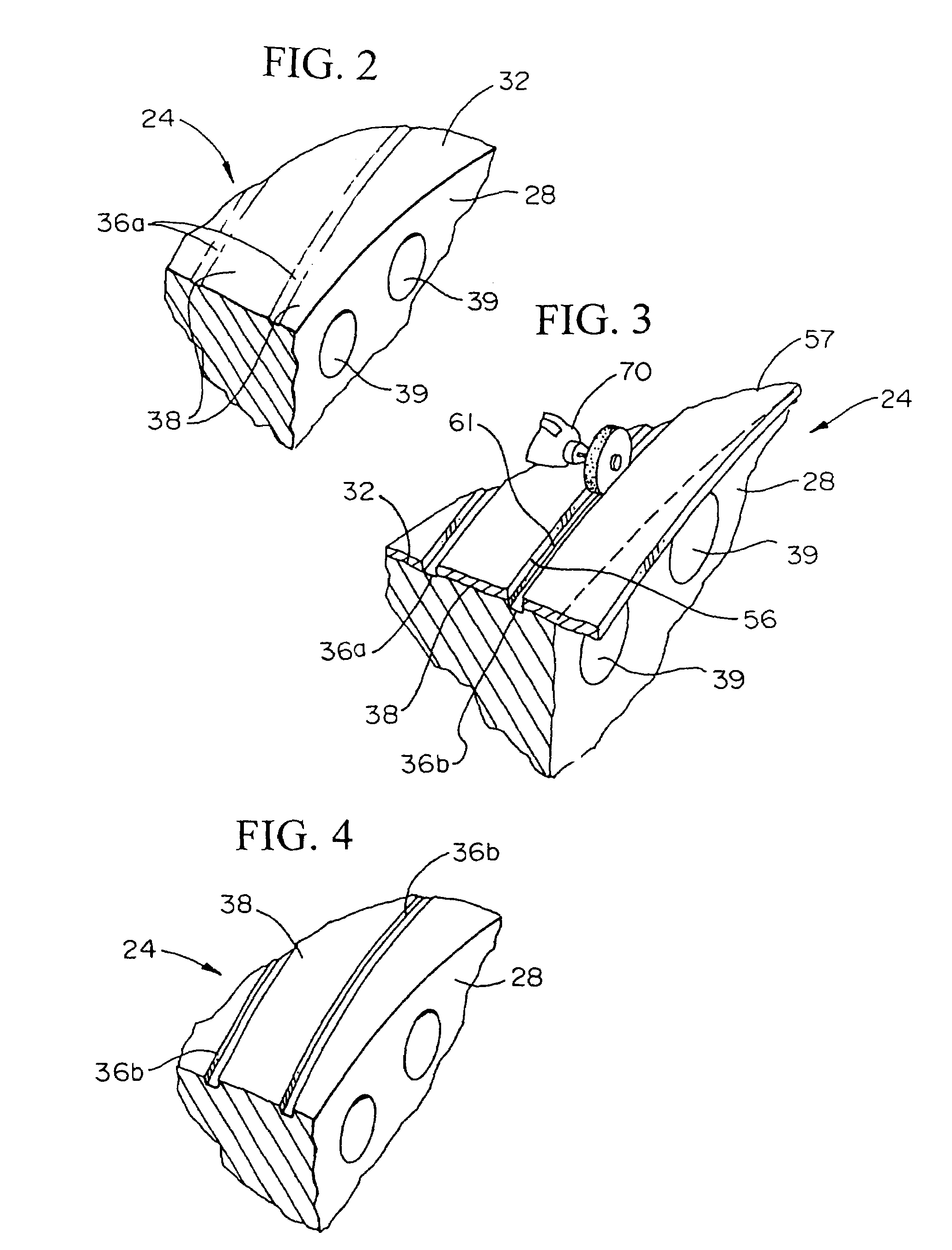
[0014]FIG. 1 is a perspective photograph of a portion of a rotating mechanism 20 from an electrical generator. The rotating mechanism 20 includes at least one collector ring 24. In general, collector rings are structures within generators or motors that are adapted and configured to interact with or to be a part of a sliding connection to complete a circuit between a fixed and a moving conductor. ...


PUM

PropertyMeasurementUnit
depthaaaaaaaaaa
depthaaaaaaaaaa
depthaaaaaaaaaa

Abstract

A method and apparatus for creating a groove in the surface of a collector ring for use in an electrical device. The method and apparatus can be used to create a new groove in the surface of a collector ring having none, or can be used to enhance or re-form an existing groove in the surface of a collector ring. In some embodiments, the groove in the surface of the collector ring is created using a cutting tool that has a cutting action that functions independently from the motion of the collector ring. In other embodiments, a masking material is positioned over a portion of the surface of the collector ring to create a masked portion and an exposed portion of the surface of the collector ring. A groove is then created in the exposed portion of the surface of the collector ring. The masking material is then removed from the surface of the collector ring.

Description

[0001]This application is a continuation of U.S. patent application Ser. No. 09 / 864,446, filed on May 24, 2001, now U.S. Pat. No. 6,652,360, wherein such document is incorporated herein by reference.FIELD OF THE INVENTION[0002]The invention is directed to a method and apparatus for processing a collector ring used in an electrical device. More particularly, the invention relates to a method and apparatus for creating a groove or grooves on the surface of collector ring used in an electrical device.BACKGROUND OF THE INVENTION[0003]It is known to provide a spiral groove in the carbon brush contact surfaces of collector rings, particularly in collector rings of large industrial electrical generators or motors, and similar machinery. The grooves can serve various purposes. For example, the grooves help to reduce selective action of the brushes, which can cause catastrophic failure of the brush to ring contacts. After wear due to prolonged use, or after turning down, or re-truing of the ...

Claims


Application Information

Patent Timeline
Patent Type & Authority Patents(United States)
IPC IPC(8): B24B1/00H01R39/08B24B19/02H01R43/08H01R43/14
CPCB24B1/00H01R43/14B24B19/022H01R43/08
Inventor CUTSFORTH, DAVID L.
Owner CUTSFORTH PRODS
Why Eureka
Try Eureka