Mechanical mounting configuration for flushmount devices

a flushmount device and mounting configuration technology, applied in the direction of instruments, machine supports, other domestic objects, etc., can solve the problems of increasing installation costs accordingly, unable to provide a secure mount for system components on either surface, and unable to meet the requirements of installation, so as to achieve secure and easy installation.

Active Publication Date: 2007-02-06
ADEMCO INC
View PDF11 Cites 52 Cited by
  • Summary
  • Abstract
  • Description
  • Claims
  • Application Information

AI Technical Summary

Benefits of technology

[0006]Therefore it would be advantageous to provide a mechanical flushmount for devices that is both secure and installs quickly and easily. In order to overcome the foregoing and other weaknesses and deficiencies in the prior art, provided by the present invention are a method and apparatus for the mechanical mounting of devices flush with a surface to which they are mounted.

Problems solved by technology

Either surface proves challenging to provide a secure mount for the system components.
This method is time-consuming and increases installation costs accordingly.
While being generally quicker and more efficient, this method provides a less secure mount.

Method used


Image

  • Mechanical mounting configuration for flushmount devices
  • Mechanical mounting configuration for flushmount devices
  • Mechanical mounting configuration for flushmount devices

Examples


Embodiment Construction

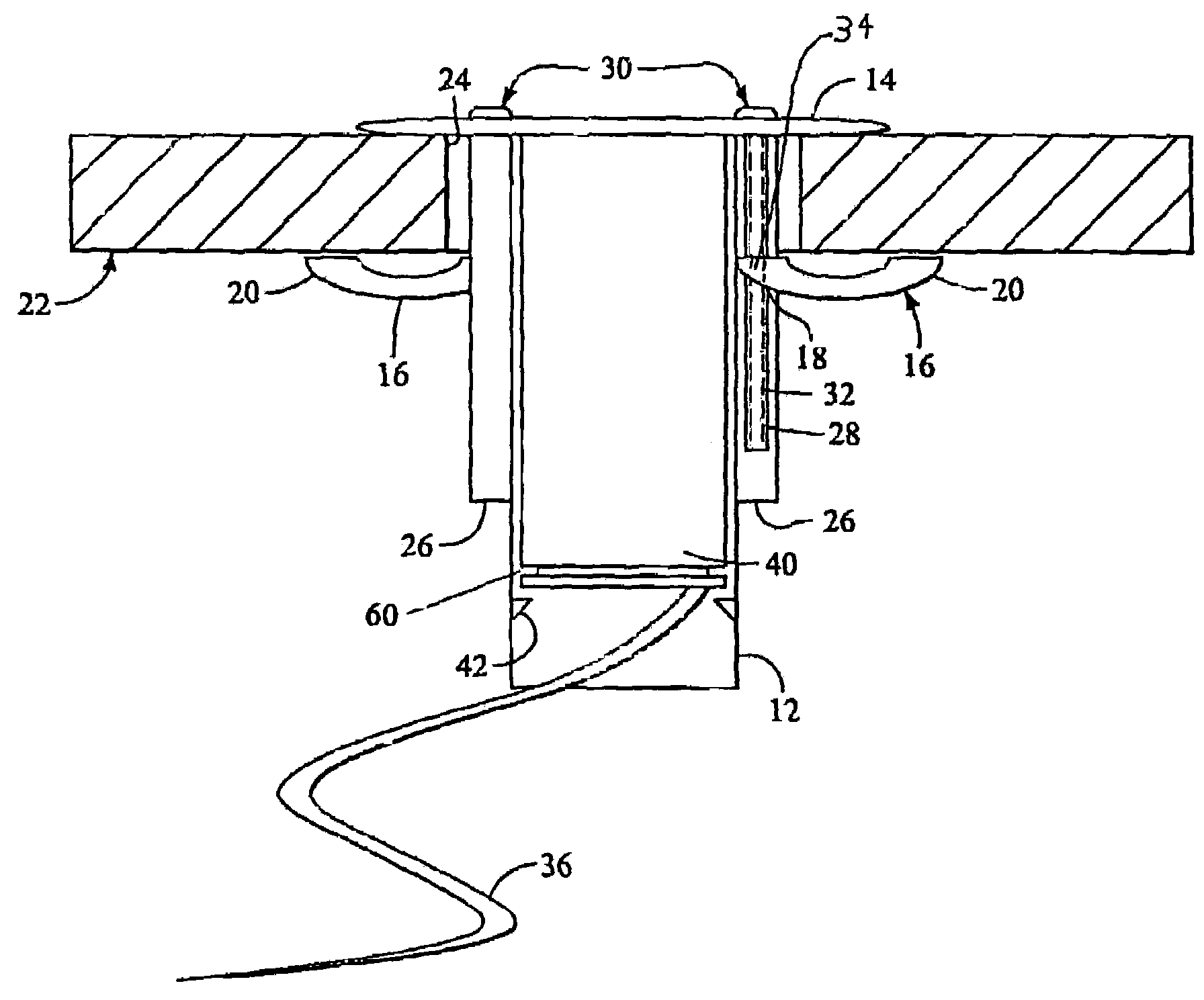
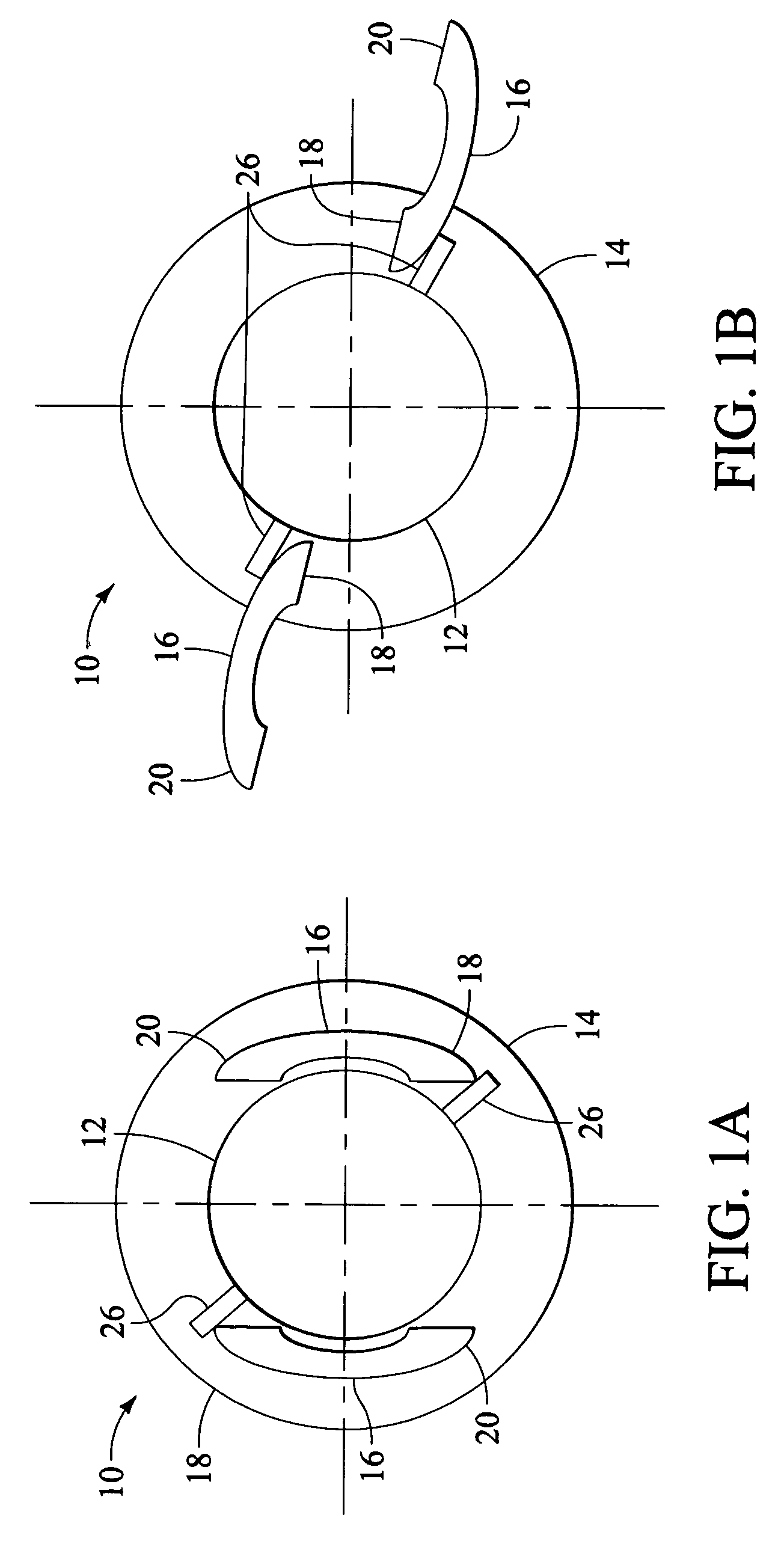
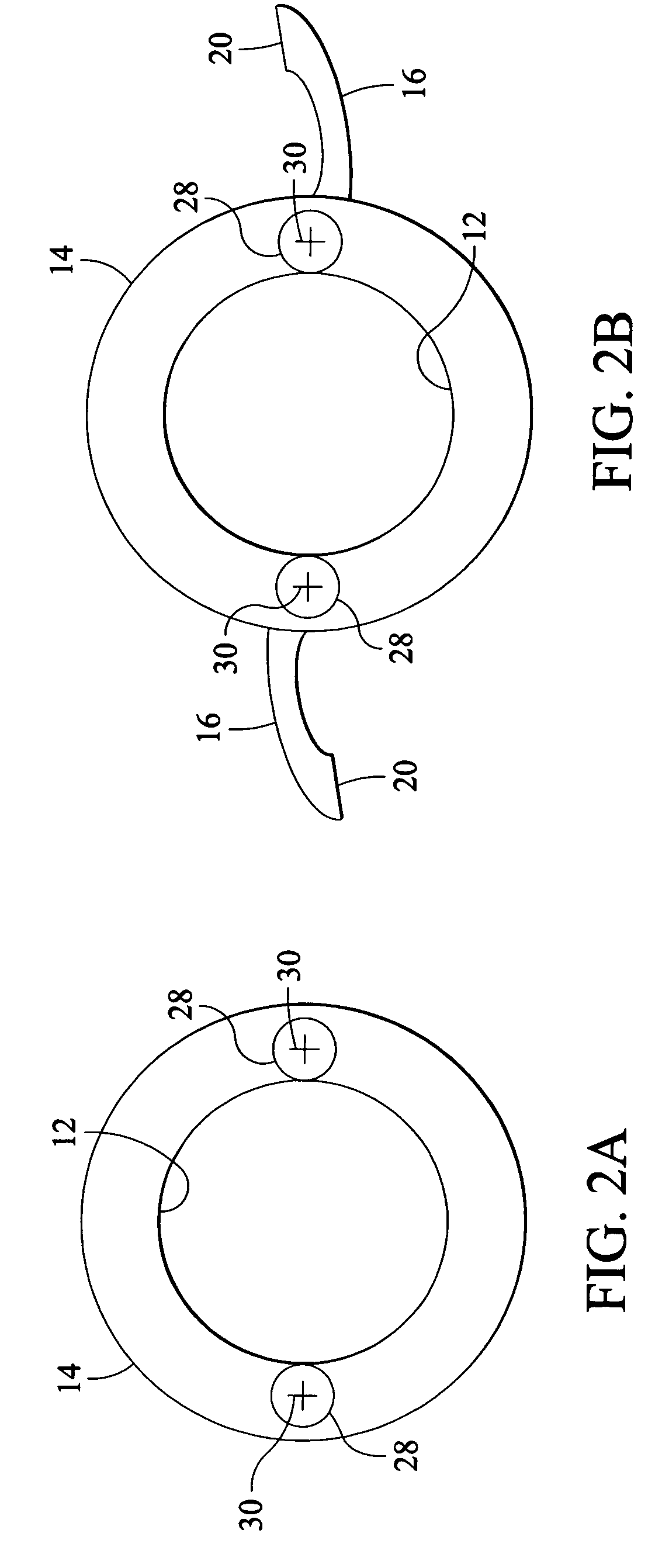
[0014]Referring now to FIGS. 1A and 1B, shown is a rear view of a flushmount device, generally 10, according to an exemplary embodiment of the present invention in closed and opened positions, respectively. Flushmount device 10 comprises an enclosure 12, in which or to which a system component would be held or secured, respectively. In this embodiment, the enclosure 12 is cylindrical, though other shapes, including but not limited to triangular, square or rectangular or other prismatic shapes, or irregular shapes, are suitable as well.

[0015]Connected with the enclosure 12 at one end thereof is a flange 14 that extends outward from the enclosure 12. In the exemplary embodiment, the flange 14 is similar in shape to the enclosure, but this need not be the case. The flange covers the opening 24 (see FIG. 3) in a panel 22 (see FIG. 3) supporting the flushmount device 10. Connected with the enclosure 12 are one or more securing arms 16, two in the exemplary embodiment. Each securing arm 1...


PUM


Abstract

A mechanical flushmount device for mounting to a panel, includes an enclosure for holding the component to be mounted, a flange at one end of the enclosure extending outward from the enclosure, at least one securing arm rotable from a closed position within the lateral extent of the flange to an open position at least partially beyond the lateral extent of the flange, and at least one actuator operable to rotate the at least one securing arm, said actuator being operable from a side of the flange opposite the securing arm.

Description

BACKGROUND OF THE INVENTION[0001]1. Field of Invention[0002]The invention relates to the field of security devices and of construction materials and methods, and more particularly to a method and apparatus for mounting system components nearly flush to the surface of a wall, floor, or ceiling.[0003]2. Description of Related Art[0004]In the installation of security systems, and in construction in general, it is often desirable to mount sensors or other system components to be flush or nearly flush with the surface into which they are mounted. More specifically, security system components including sensors designed to detect heat, motion, sound, light, water, or the like, or input keypads, key cylinders or the like, are preferably mounted flush to a wall, ceiling, or other surface, in order to be inconspicuous and / or unobtrusive. Generally, those surfaces are walls comprised of wallboard and studs, or ceilings, specifically false or so-called ‘drop’ ceilings. Either surface proves cha...

Claims


Application Information

Patent Timeline
Patent Type & Authority Patents(United States)
IPC IPC(8): G12B9/00
CPCF16B13/0808
Inventor PIEL, KEVIN G.ADONAILO, ROBERT S.MARTIN, CHRISTOPHER D.BABICH, THOMAS S.
Owner ADEMCO INC
Why Eureka
Try Eureka