
Suction tip for dental treatment

a technology for dental treatment and suction tip, which is applied in the field of suction tip for dental treatment, can solve the problems of easy deformation, discomfort of patients, and easy discomfort of patients, and achieve the effect of facilitating suction operation or

Inactive Publication Date: 2007-02-06
HASEGAWA MINAKO
View PDF10 Cites 3 Cited by
  • Summary
  • Abstract
  • Description
  • Claims
  • Application Information

AI Technical Summary

Benefits of technology

"The invention provides a suction tip for dental treatment that is made of silicone rubber and has a soft end portion and a hard base portion. This design prevents discomfort for patients and ensures the strength of the tip for easy suction or attachment. Additionally, the flavoring added to the end portion of the tip helps to relax patients and spread the flavor."

Problems solved by technology

However, although made of a rubber material such as silicone rubber, the conventional suction tip for dental treatment sometimes causes a patient discomfort such as an uncomfortable feeling or pain when its end portion touches the gingiva or oral cavity mucosa of the patient.
It is possible to use soft silicone rubber as a material of the suction tip for dental treatment, but this causes a problem that the entire strength of the suction tip reduces to cause it deformation easily, making a suction operation and an attachment operation to the suction tube difficult.

Method used


Image

  • Suction tip for dental treatment
  • Suction tip for dental treatment
  • Suction tip for dental treatment

Examples


first embodiment

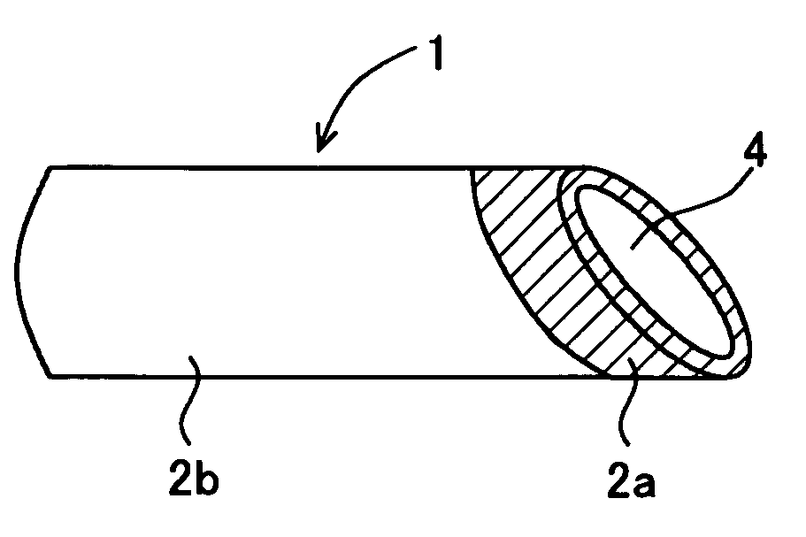
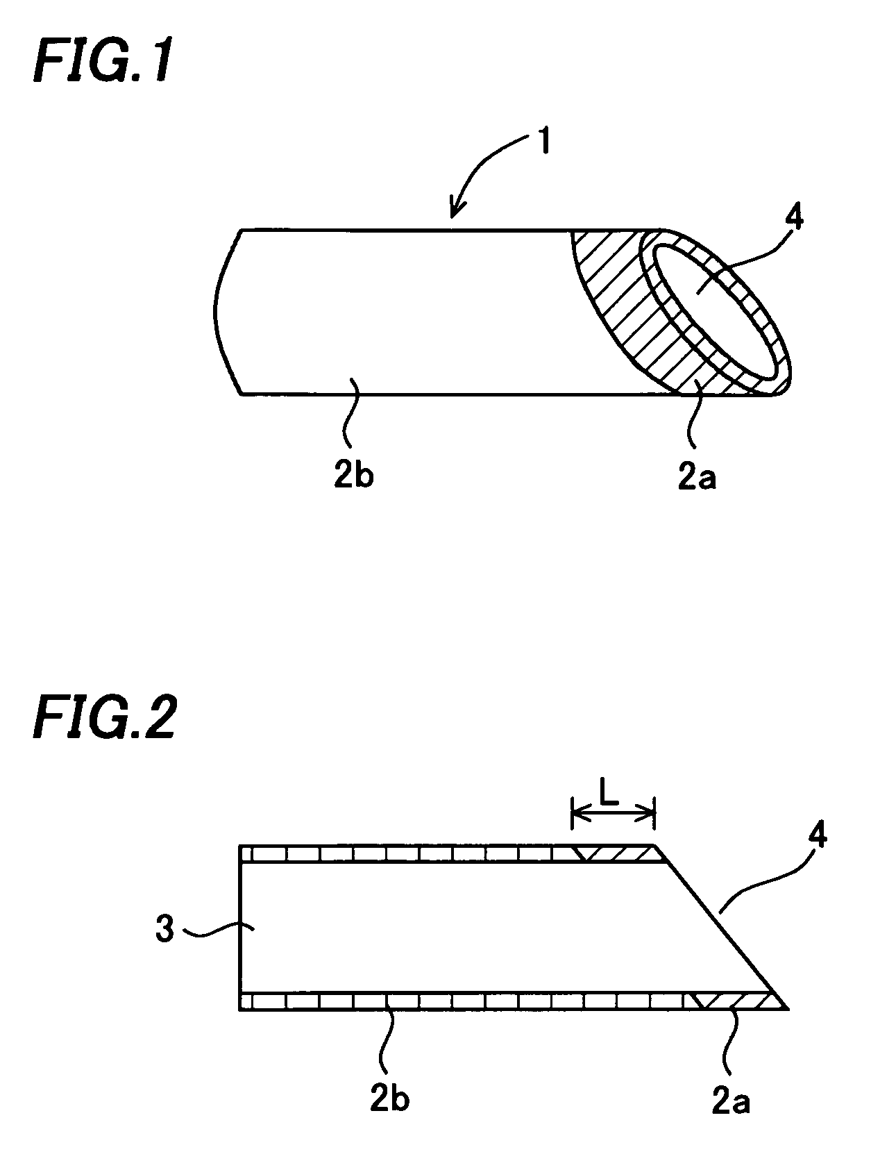
[0016]A suction tip for dental treatment of the invention will be described with reference to FIGS. 1 and 2. FIG. 1 is a perspective view of this suction tip for dental treatment 1, and FIG. 2 is a cross-sectional view of the suction tip 1 along its longitudinal direction.

[0017]The suction tip for dental treatment 1 has a cylindrical shape as a whole, of which a front end portion of the cylinder is cut obliquely and a back end portion is cut vertically, forming a back end opening portion 3 and a front end opening portion 4. A front end portion 2a which is to touch the gingiva or oral cavity mucosa of a patient is made of soft silicone rubber, and a remaining cylindrical base portion 2b continuing to this front end portion 2a is made of hard silicone rubber. The soft silicone rubber forming the front end portion 2a is gel (jellied) silicone rubber, and its penetration index is 80 to 90 mm, preferably.

[0018]The hardness of the silicone rubber can be measured by a penetration test. The...

second embodiment

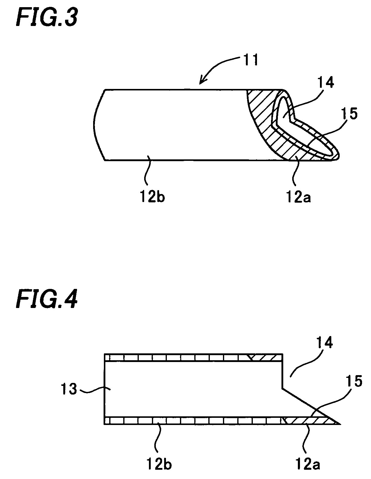
[0024]Next, a suction tip for dental treatment of the invention will be described with reference to FIGS. 3 and 4. FIG. 3 is a perspective view of this suction tip for dental treatment 11, and FIG. 4 is a cross-sectional view of the suction tip 11 along its longitudinal direction.

[0025]This suction tip for dental treatment 11 is also a cylindrical tube, and has a back end opening portion 13 and a front end opening portion 14. A front end portion 12a which is to touch the gingiva or oral cavity mucosa of a patient is made of soft silicone rubber, and a cylindrical base portion 12b other than the front end portion 12a is made of hard silicone rubber.

[0026]This suction tip for dental treatment 11 differs from the one of the first embodiment in that an extended portion 15 extending from an edge of the front end opening portion 14 like a tongue is formed. Since mainly this extended portion 15 touches the gingiva or oral cavity mucosa of a patient, the front end portion 12a including this...


PUM


Abstract

The invention provides a suction tip for dental treatment which has no possibility of causing a patient discomfort such as pain when its end portion touches the gingiva or oral cavity mucosa of the patient, and enables an easy suction operation and an easy attachment operation to a suction tube by its secured entire strength. The suction tip for dental treatment has a cylindrical shape as a whole, a front end portion of the cylinder is cut obliquely, and a back end portion thereof is cut vertically, thereby forming a back end opening portion and a front end opening portion. A front end portion which is to touch the gingiva or oral cavity mucosa of a patient is made of soft silicone rubber, and a cylindrical base portion continuing to this front end portion is made of hard silicone rubber. The soft silicone rubber forming the front end portion is gel silicone rubber.

Description

CROSS-REFERENCE OF THE INVENTION[0001]This invention is based on Japanese Patent Application No. 2005-063312, the content of which is incorporated by reference in its entirety.BACKGROUND OF THE INVENTION[0002]1. Field of the Invention[0003]The invention relates to a suction tip for dental treatment detachably attached to an end portion of a suction tube of a vacuum device.[0004]2. Description of the Related Art[0005]In dental treatment, a vacuum device is used for sucking saliva and so on in an oral cavity of a patient to remove these from the oral cavity. A cylindrical suction tip made of silicone rubber is attached to an end portion of a suction tube of the vacuum device so that the end portion of the suction tube does not directly touch the gingiva or oral cavity mucosa of a patient.[0006]The relevant technology is described in the Japanese patent application publications Nos. 2005-13394 and 2004-321710 and the Japanese utility model application publications Nos. sho 58-124117 an...

Claims


Application Information

Patent Timeline
Patent Type & Authority Patents(United States)
IPC IPC(8): A61C17/06
CPCA61C17/043A61C17/08
Inventor HASEGAWA, MINAKO
Owner HASEGAWA MINAKO
Learn More