Releasable coupling assembly

a technology of coupling assembly and bolt, which is applied in the direction of rod connection, fastening means, constructions, etc., can solve the problems of imposing a risk of harm to the operator, unable to provide substantial tightening of the point onto the adapter, and exacerbate the difficulty and risk attendant, so as to achieve effective tightening of the wear member onto the support structure, the effect of reducing the risk and being convenient to us

Inactive Publication Date: 2007-02-13
ESCO GRP LLC
View PDF44 Cites 110 Cited by
  • Summary
  • Abstract
  • Description
  • Claims
  • Application Information

AI Technical Summary

Benefits of technology

[0011]The present invention pertains to an improved coupling assembly for releasably holding separable parts together in a secure, easy, and reliable manner. Further, the lock of the present invention can be installed and removed simply by using a manual or powered wrench. The need to hammer or pry the lock into and out of the assembly is eliminated.
[0012]The present invention is particularly useful for securing a wear member to a support structure in conjunction with an excavating operation. The lock of the present invention is easy to use, is securely held in the wear assembly, alleviates the risk associated with hammering a lock into and out of a wear assembly, and operates to effectively tighten the wear member onto the support structure.
[0013]In one aspect of the invention, a tapered lock member is formed with a threaded formation that is used to pull the lock member into a locking position in the assembly. The lock member, then, bears against the assembly to hold the components of the assembly together. The use of a threaded formation on the lock member also reduces the risk that the lock member will be ejected during use as compared to a lock that is simply hammered into place.

Problems solved by technology

Such hammering of the lock is an arduous task and imposes a risk of harm to the operator.
However, as can be appreciated, an increase in the tightness in which the lock is received in the opening further exacerbates the difficulty and risk attendant with hammering the locks into and out of the assemblies.
The lock additionally often lacks the ability to provide substantial tightening of the point onto the adapter.
While a rubber insert will provide some tightening effect on the tooth at rest, the insert lacks the strength needed to provide any real tightening when under load during use.
Most locks also fail to provide any ability to be re-tightened as the parts become worn.
Moreover, many locks used in teeth are susceptible to being lost as the parts wear and the tightness decreases.
These difficulties are not limited strictly to the use of locks in excavating teeth, but also apply to the use of other wear parts used in excavating operations.
While the point experiences the most wear in a tooth, the adapter will also wear and in time need to be replaced.
As with the mounting of the points, hammering of the wedges into the openings is a difficult and potentially hazardous activity.
In many assemblies, other factors can further increase the difficulty of removing and inserting the lock when replacement of the wear member is needed.
For example, the closeness of adjacent components, such as in laterally inserted locks (see, e.g., U.S. Pat. No. 4,326,348), can create difficulties in hammering the lock into and out of the assembly.
Fines can also become impacted in the openings receiving the locks making access to and removal of the locks difficult.
This orientation of the bucket can make lock removal difficult and hazardous as the worker must access the opening from beneath the bucket and drive the wedge upward with a large hammer.
The risk is particularly evident in connection with dragline buckets, which can be very large.
Also, because wedges can eject during service, it is common practice in many installations to tack-weld the wedge to its accompanying spool, thus, making wedge removal even more difficult.
While these devices eliminate the need for hammering, they each require a number of parts, thus, increasing the complexity and cost of the locks.
The ingress of fines can also make removal difficult as the fines increase friction and interfere with the threaded connections.
Moreover, with the use of a standard bolt, the fines can build up and become “cemented” around the threads to make turning of the bolt and release of the parts extremely difficult.

Method used


Image

  • Releasable coupling assembly
  • Releasable coupling assembly
  • Releasable coupling assembly

Examples


Embodiment Construction

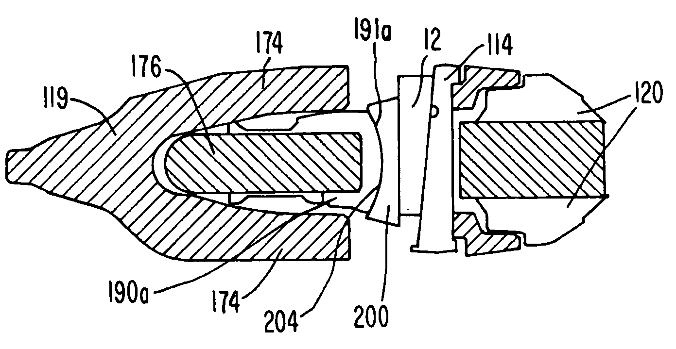
[0045]The present invention pertains to a coupling assembly for releasably holding separable parts together. While the invention has a broader application, it is particularly useful in releasably securing a wear member to a support structure in an excavating operation. The wear member may, for example, be a point, an adapter, a shroud or other replaceable component.

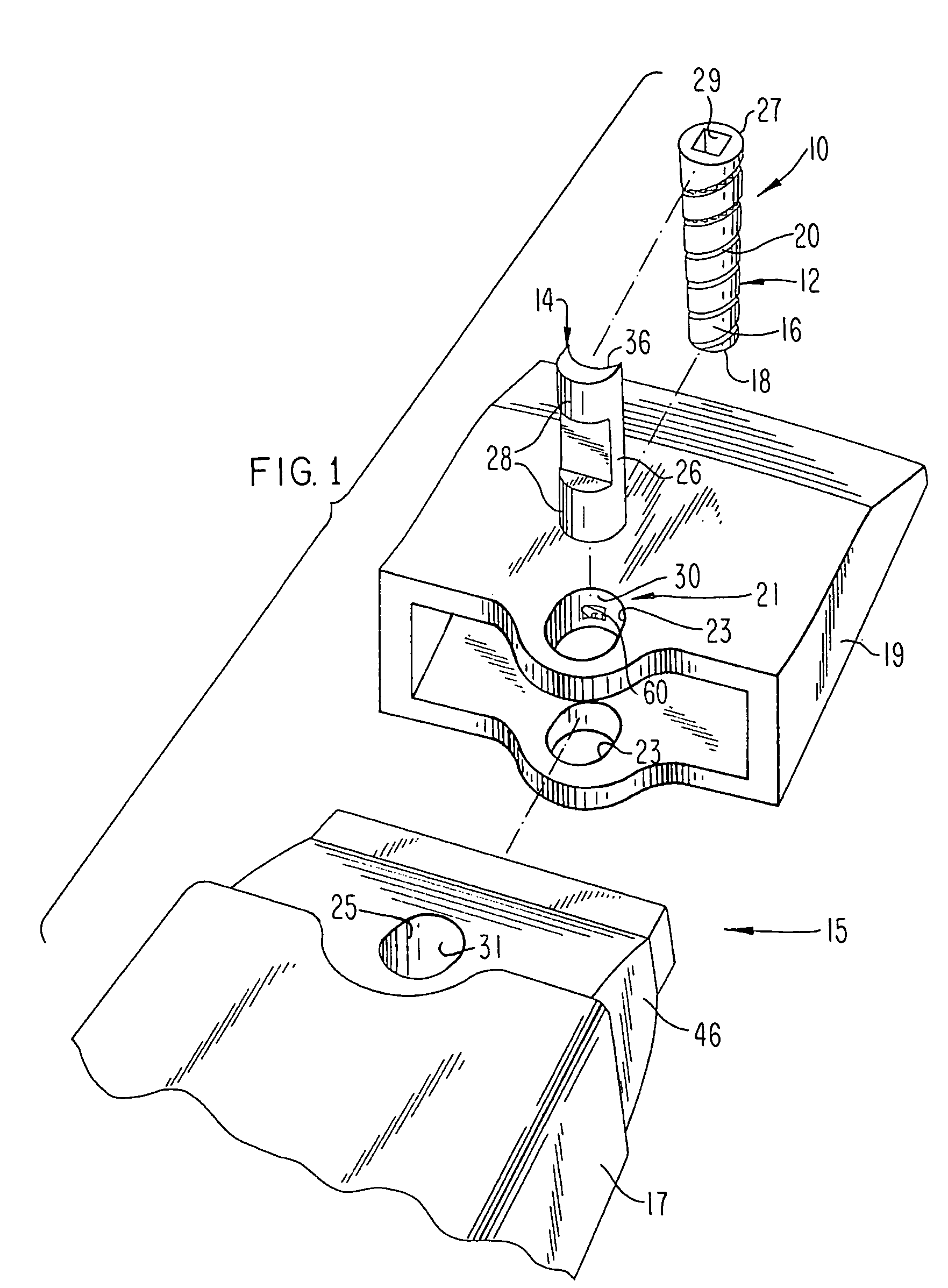
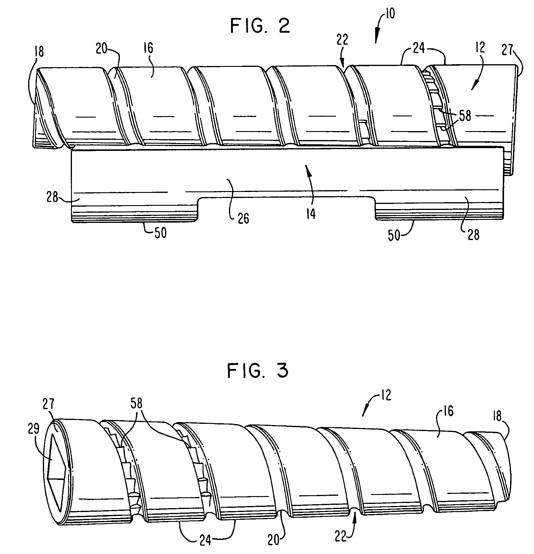
[0046]In one preferred construction, the lock 10 includes a wedge 12 and a spool 14 (FIGS. 2–5). Although the lock can be used to secure a wide range of components together, it is shown in FIG. 1 holding together the parts of an excavator tooth. In this embodiment of the invention, the lock is placed in a wear assembly 15 wherein the support structure is formed as an adapter 17 and the wear member is defined as a point or tip 19. Lock 10 is received into an opening 21 in wear assembly 15 that is cooperatively defined by holes 23 in point 19 and hole 25 in adapter 17 so as to releasably hold the point to the adapter (FIGS....


PUM


Abstract

A lock that includes a wedge that is used to releasably secure separable components of an assembly together. The wedge can be used with a spool. The wedge and spool are threadedly coupled together to drive the wedge into and out of an opening in the assembly without hammering or prying. The direct coupling of the wedge and spool eliminates the need for bolts, washers, nuts and other hardware so as to minimize the number of parts. As a result, the lock is inexpensive to make, easy to use, and unlikely to become inoperative because of lost or broken parts or due to fines or other difficulties encountered in harsh digging environments. Further, the wedge can be driven into the assembly to provide the degree of tightness necessary for the intended operation and / or to re-tighten the assembly after incurring wear during use. A latch assembly is preferably provided to securely hold the wedge in place and avoid an undesired loss of parts during use.

Description

[0001]This application is a continuation in part of U.S. Ser. No. 10 / 425,934 filed Apr. 30, 2003.FIELD OF THE INVENTION[0002]The present invention pertains to a coupling assembly for releasably securing separable parts together, and especially for securing together components of a wear assembly used in excavating or the like.BACKGROUND OF THE INVENTION[0003]Excavating equipment typically includes various wear parts to protect underlying products from premature wear. The wear part may simply function as a protector (e.g., a wear cap) or may have additional functions (e.g., an excavating tooth). In either case, it is desirable for the wear part to be securely held to the excavating equipment to prevent loss during use, and yet be capable of being removed and installed to facilitate replacement when worn. In order to minimize equipment downtime, it is desirable for the worn wear part to be capable of being easily and quickly replaced in the field. Wear parts are usually formed of three...

Claims


Application Information

Patent Timeline
Patent Type & Authority Patents(United States)
IPC IPC(8): E02F9/28
CPCE02F9/2833E02F9/2841E02F9/2883Y10T403/7069Y10T403/7056E02F9/2808
Inventor BRISCOE, TERRY L.
Owner ESCO GRP LLC
Why Eureka
Try Eureka