Anatomical imaging system with centipede belt drive

anatomical imaging and centipede technology, applied in the direction of instruments, patient positioning for diagnostics, applications, etc., can solve the problems of time-sensitive effect of particular treatments, frequent “round-trip” time between the emergency room, radiology department (where the ct machine is typically located) and other problems, to achieve the effect of reducing diagnostic time, convenient transportation, and favorable image quality

Active Publication Date: 2007-02-13
NEUROLOGICA CORP
View PDF9 Cites 60 Cited by
  • Summary
  • Abstract
  • Description
  • Claims
  • Application Information

AI Technical Summary

Benefits of technology

[0012]The present invention comprises a new and improved anatomical imaging system which addresses the foregoing problems. More particularly, the present invention comprises a small, mobile CT machine that can be moved to the patient so that the patient can be scanned at their current location, thus dramatically reducing diagnostic times. The mobile CT machine can be located in the emergency room, is easy to transport directly to the patient's bedside, and provides image quality favorably comparable to traditional, fixed-location CT machines which require patient transport.
[0013]In essence, the new CT machine eliminates traditional transportation delays by allowing patients to be scanned in the emergency room, while remaining on their gurney.
[0014]More particularly, with a conventional CT machine, the CT machine is fixed in place, typically in the radiology department. The patient is moved to the CT machine, placed on a precision-advancement patient platform and then, with the scanning apparatus remaining stationary, the patient is advanced into the scanning zone of the CT machine using the precision-advancement patient platform. In contrast, with new CT machine of the present invention, the patient remains in the emergency room on their gurney, the CT machine is moved to the patient and then, while the patient remains stationary, the CT machine is precision-advanced relative to the patient so that the scanning zone of the CT machine moves relative to the patient. Thus, the new CT machine of the present invention can be wheeled into position in an emergency room and the patient scanned while remaining on their gurney, without ever having to move the patient from the emergency room to the radiology department, and then off the gurney and onto the moving platform of a traditional, fixed-location CT machine.

Problems solved by technology

This is because treatments for ischemic strokes may be contra-indicated for treatment of hemorrhagic strokes and, furthermore, the effectiveness of a particular treatment can be time-sensitive.
Unfortunately, however, the “round-trip” time between the emergency room (where the patient is typically first received) and the radiology department (where the CT machine is typically located) can frequently take up to several hours, even in the best hospitals.
As a result, the time spent in transporting the patient from the emergency room to the CT machine and back again can consume critical time which can compromise treatment of the patient.

Method used


Image

  • Anatomical imaging system with centipede belt drive
  • Anatomical imaging system with centipede belt drive
  • Anatomical imaging system with centipede belt drive

Examples


Embodiment Construction
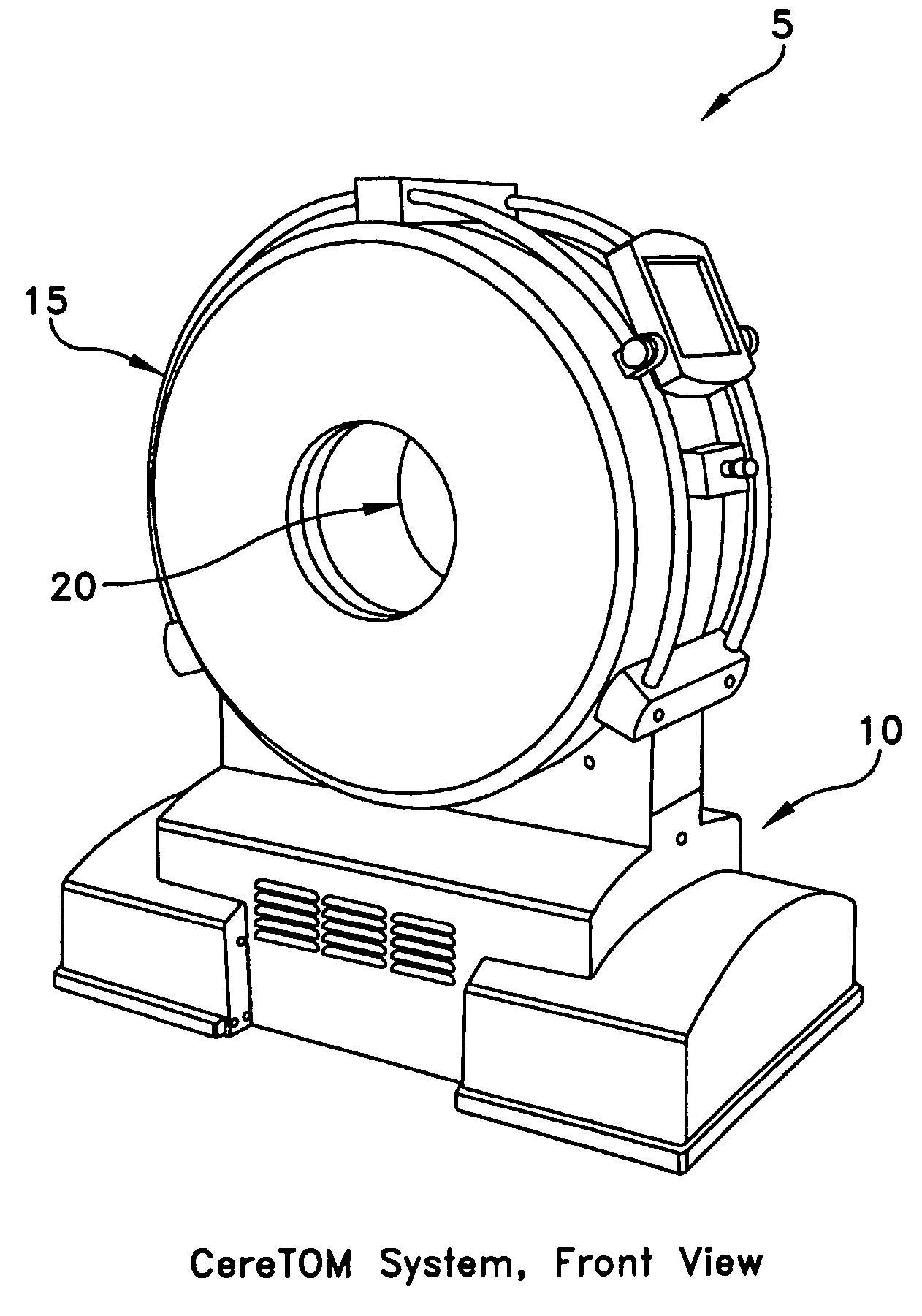
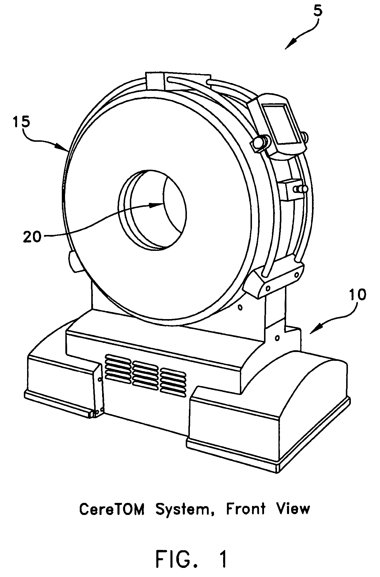
CT Machine 5

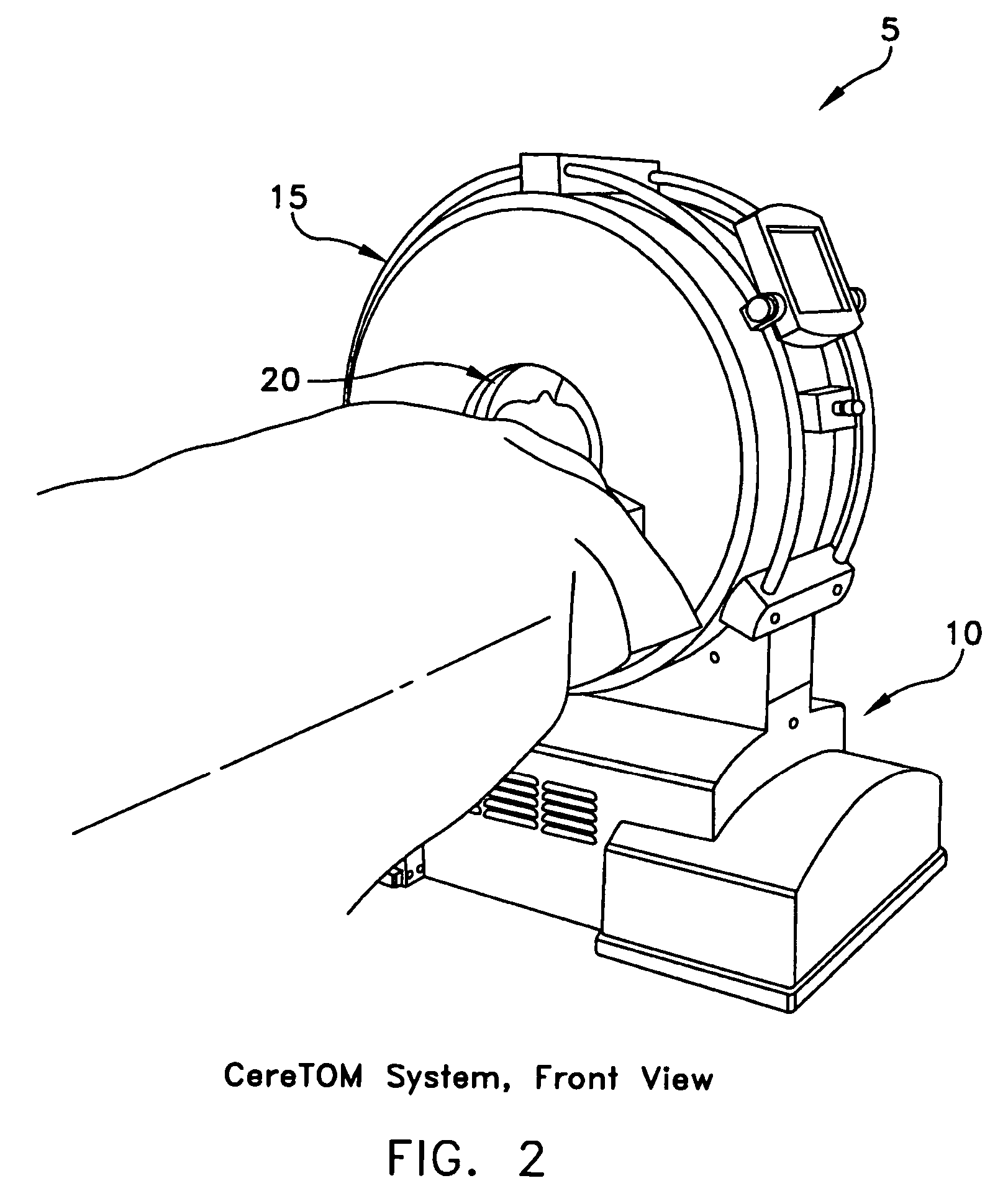
[0051]Looking first at FIGS. 1–6, there is shown a novel CT machine 5 formed in accordance with the present invention. CT machine 5 generally comprises a base 10 which supports a torus 15. Torus 15 defines a center opening 20. Base 10 and torus 15 together comprise the CT scanning apparatus which is used to scan the patient anatomy positioned in center opening 20. Such scanning apparatus typically comprises a rotating X-ray source and X-ray detector, and various electronic hardware and software for controlling the apparatus and processing the acquired data so as to generate the CT scans. Such scanning apparatus may be of the sort well known in the art.

[0052]CT machine 5 also comprises the novel transport mechanism 100 which will hereinafter be discussed.

Transport Mechanism 100

[0053]As noted above, CT machine 5 is intended to be moved to the patient, and then scan the patient while the patient remains stationary on their gurney.

[0054]To this end, in one preferred form of ...


PUM


Abstract

An anatomical imaging system comprising a CT machine; and a transport mechanism mounted to the base of the CT machine, wherein the transport mechanism comprises a fine movement mechanism for moving the CT machine precisely, relative to the patient, during scanning.

Description

REFERENCE TO PENDING PRIOR PATENT APPLICATIONS[0001]This patent application claims benefit of:[0002](i) pending prior U.S. Provisional Patent Application Ser. No. 60 / 670,164, filed Apr. 11, 2005 by Andrew P. Tybinkowski et al. for ANATOMICAL IMAGING SYSTEM WITH CENTIPEDE DRIVE; and[0003](ii) pending prior U.S. Provisional Patent Application Ser. No. 60 / 593,001, filed Jul. 30, 2004 by Bernard Gordon et al. for ANATOMICAL SCANNING SYSTEM.[0004]The two above-identified patent applications are hereby incorporated herein by reference.FIELD OF THE INVENTION[0005]This invention relates to anatomical imaging systems in general, and more particularly to anatomical imaging systems of the sort utilizing Computurized Tomography (CT) systems and the like.BACKGROUND OF THE INVENTION[0006]Strokes are the third leading cause of death in the United States (causing approximately 177,000 deaths per year) and the number one cause of long-term disability (affecting nearly 5 million people). Strokes resu...

Claims


Application Information

Patent Timeline
Patent Type & Authority Patents(United States)
IPC IPC(8): H05G1/02H05G1/00
CPCA61B6/032A61B6/04A61B6/4405A61B6/501G01N23/046A61B6/4488G01N2223/612G01N2223/419
Inventor TYBINKOWSKI, ANDREW P.BAILEY, ERIC M.ALLIS, DANIEL
Owner NEUROLOGICA CORP
Why Eureka
Try Eureka